A Bridge Over Troubled Moisture

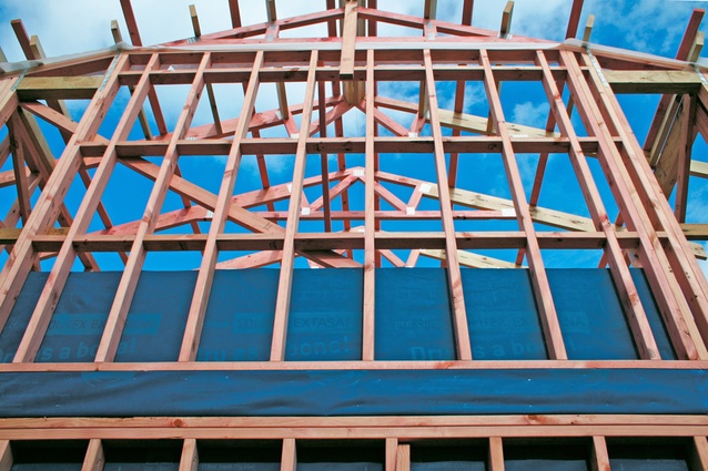
Previous article on metal back pans investigated the likelihood of creating condensation behind metal back pans on the outside of insulated apartment walls. The intent of the article was to highlight the failure of vapour impermeable sheathing materials in managing moisture in the building envelope. The article received some constructive feedback. As we move forward, we not only need to consider the detail of how the material layers are arranged but also the thermal effects of the structure that physically holds up the water, air, vapour and thermal control layers. In the case of metal framed structures that hold up the internal lining, wind brace sheathing, water barrier membranes and air barrier systems, then we need to consider the issue of exacerbated thermal bridging and its effect on localised mould growth risk.
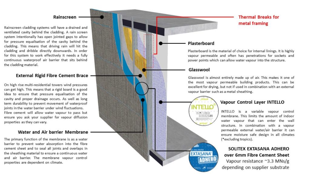
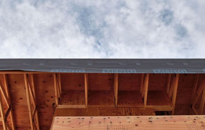
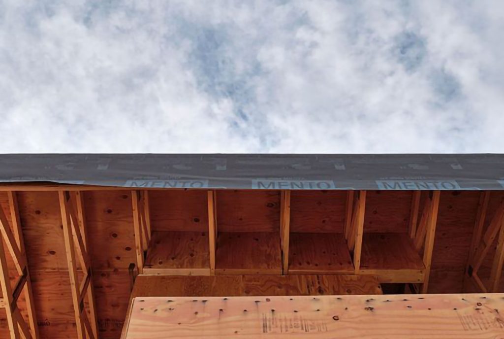
Figure 1. Preventing moisture accumulation in steel structure, including preventing cold bridging
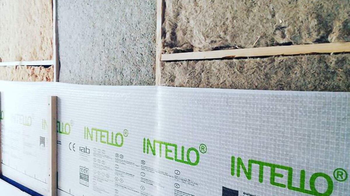
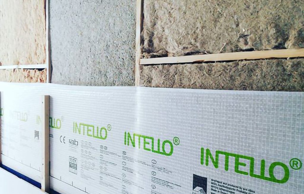
Metal framing in direct contact with the outside can easily cause localised cold spots on the interior surface of the wall. This raises an issue from a health perspective as well as the performance of the INTELLO® layer. Localised cold spots could result in elevated relative humidity at the interface between the studs and the plasterboard, creating conditions suitable for mould growth at the INTELLO® layer where it is in contact with the metal studs.
Addressing the thermal bridging isn’t necessarily the whole story, lowering the indoor humidity through correctly designed and controlled ventilation is also important and beneficial from an indoor moisture management perspective (treat the source of moisture) but can be addressed in another article.
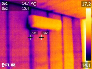
Figure 2. Thermal bridges create cool spots on the internal linings
Figure 2 highlights the effect of exacerbated thermal bridging in an apartment in Canberra. This apartment has clearly visible cold bridges at the studs which can increase moisture content of the plasterboard at the studs and localised high humidity at the plasterboard.
Let’s take a look at how to avoid this and the potential for mould growth at the plasterboard layer. Taking a look at the thermal bridging through the studs there are various ways you could thermally break this. But what degree of thermal breaks are required for optimal outcomes and what is the R-value required to keep the internal surface warm enough to prevent mould?
The NCC currently requires R0.2 thermal breaks if there is steel cladding on steel studs. So I have used this as a test case. Let’s see if it works.
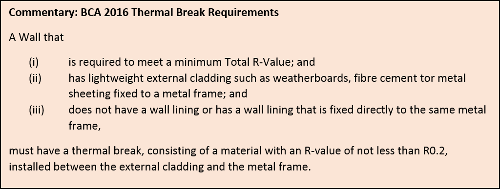
Now we are in 2019 we need to prepare ourselves for the new 2019 BCA requirements which call up NZS 4214 a secondary reference to account for thermal bridging in R-value calculations. Interestingly, NZS 4214 has been a secondary refence in the building code through AS/NZS 4859.1:2002 since energy efficiency provisions were introduced in the BCA in the early 2000’s. It has just been completely ignored by industry and is now highlighted in the new version of AS/NZS 4859.2:2018 R-value calculation methodology.
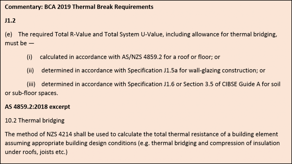
AUTHORS NOTE: NZ 4214 addresses thermal bridging and calculation of R-Values and will be called up via AS/NZS 4859.2 reference in 2019 BCA Volume 1. Please be aware of sheathing thermal breaks and the ability to manage condensation in accordance with section F6 Condensation Management. See here for a discussion on the issue.
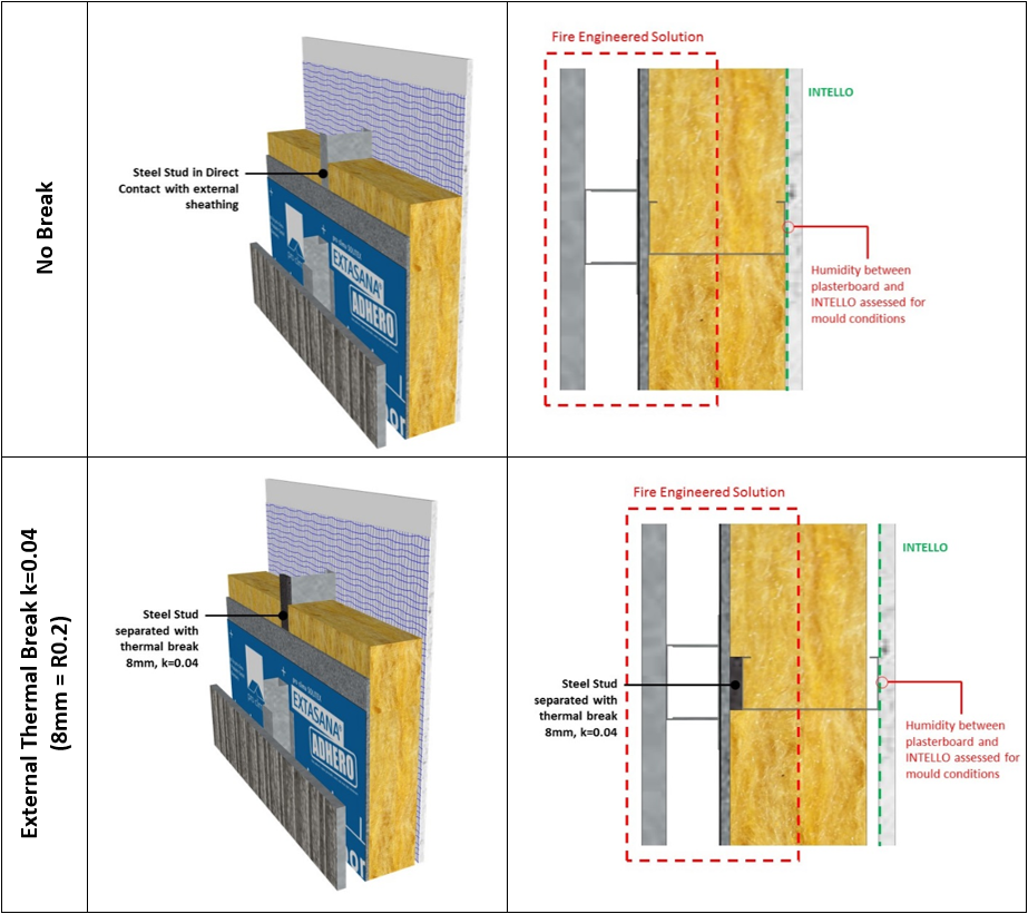
Table 1. Thermal break options; No break vs External break (R0.2)
Mould thrives at certain temperature and humidity conditions. At lower temperatures below 5°C mould struggles to grow, that’s why we used refrigerators to preserve our food. It happens that the temperatures humans like to live at mould also likes, around 20-30°C, give it some water by adding humidity to fill the spores (conditions above 75% RH) and you have a perfect climate for mould germination to occur.
Cold bridging through the studs can cause localised high humidity as the warm moist internal air comes in contact with the internal side of the cold studs. This drives up the relative humidity and creates localised conditions conducive to mould growth, this mould is often seen along the stud lines coincident with the cold bridges shown in figure 2.
Figure 3 shows the limit at which mould is likely to grow at different temperatures and the lowest threshold by which conditions are “safe” as to not induce any mould growth for common mould and dangerous mould species. These form the basis of the design thresholds to not exceed at cold bridges.
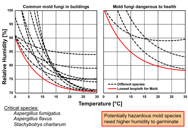
Figure 3. Temperature and humidity conditions for mould growth. Source: Fraunhofer IBP
If we keep surface conditions below the “safe” relative humidity and temperature thresholds as shown in figure 3 then mould cannot grow. Given the nature of thermal transfer exacerbated cold bridges can lead to localised high humidity conditions above these thresholds for periods of time. Then the duration at high humidity needs to also be assessed as time is a fundamental factor for mould growth.
Using WUFI® 2D 4.1 Software analysis it is possible to simulate the effects at the facade locations shown in Table 1 against the thresholds in Figure 3. Being a full dynamic simulation software the time (duration) of mould favourable conditions can be assessed. Fraunhofer Institute for Building physics has carried out much research on mould growth conditions and has a WUFI® BIO software tool enabling the assessment of mould growth.
Viitanen and Ojanen from the VTT Technical Research Centre of Finland concurrently developed a similar model to predict mould growth in building materials which has successively been adopted into the ASHRAE 160 – 2016 Criteria for Moisture Control Design Analysis in Buildings. The calculation methodology can be used to assess the health outcomes of different building details by predicting temperature and humidity at any location within the construction system. In the case presented in this article the position directly behind the metal studs on the plasterboard paper facing adjacent the INTELLO® was assessed (see table 1).
The algorithms in ASHRAE 160 derive a mould index from the VTT model. A mould index of three (M = 3) is described as visual findings of mould on the surface with <10% coverage, or <50% coverage of mould under microscope. Mould index values less than three correspond with growth visible only under microscope.
An external break R0.2 located between the metal stud and the fibre cement sheathing can reduce the internal high humidity conditions localised at the studs. The higher the R-value of the break the better at keeping the internal surface warmer and conditions at lower humidity. Figure 4 shows R0.2 is not enough to completely eliminate the risk in Canberra,so we need higher thermal breaks for energy efficiency and health.

Figure 4. Mould growth indices calculated in accordance with ASHRAE 160; Canberra, south wall. External Break vs Rm0.2 k=0.04; Acceptable below limit 3.
Table 2 shows what works and what may be risky from the thermal break option outlined in this article. Green indicates acceptable outcome, red or yellow indicate the inclusion of a thermal break or a better thermal break are required.
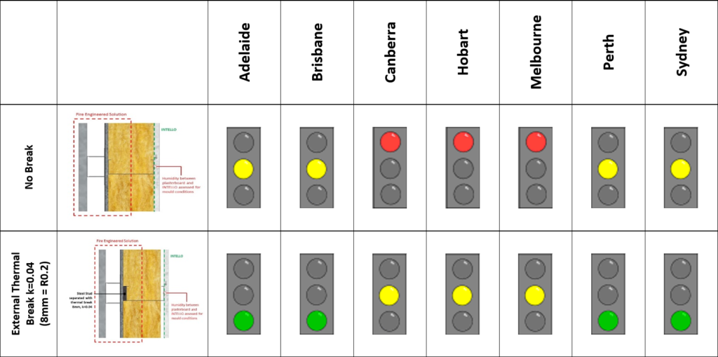
Table 2. Mould growth indicators for unbroken and thermally broken studs
The signal light presents a general assessment of the mould growth risk and the severity of the infestation (if any). ASHRAE 160; Mould index up to 1 is usually acceptable. Mould index from 1 to 3 requires additional investigations or remedies. Mould index greater than 3 is usually not acceptable. This signal light is only a guideline and represents the current state of technology.
It is also possible to add internal thermal breaks by adding spacers between plasterboard and the studs. The only drawback here is the loss of saleable floor space albeit with enhanced thermal resistance and reduced risk or mould.
The rule here is: Never have INTELLO® directly touch any inside to outside thermally conducting materials.
This brings the discussion to better thermal breaks for energy and health outcome which will be taking place in BCA 2019 with a direct reference to NZS 4214, a topic for future discussion. Energy vs health as a driver for thermal breaks means we need to consider strip breaks Vs sheathing breaks and the ability to manage moisture in the construction at the same time. External insulative sheathing should be considered in conjunction with section F6 Condensation Management. See here for one of my previous discussions on the risks associated with vapour impermeable external sheathing insulation foams.
WUFI® Pro & WUFI® 2D training will be taking place this year and can be booked online for Australia or New Zealand enabling compliance with BCA 2019 section F6 condensation management and the NZBC respectively.
