
Above Sheathing Ventilation – Part 2: The Blue Planet

Earth is just a pale blue dot in the context of our solar system. It’s a pretty wet world, 70% is covered in water. Our planet’s blue colour is the result of all this water reflecting blue wavelengths of light from the Sun. As inhabitants of this world, we are quite wet too and we do things inside our buildings that are wet. How then, do we keep our buildings dry when there’s water all around?
Weather on the Outside
The sun shining on our wet planet creates the forces that combine to create weather. Clouds are formed from water vapour carried by powerful upward air currents. The absorbed portion of heat from the sun vapourises Earth’s surface water and moves some of this water vapour away from the Earth. At cooler high altitudes, the vapour condenses to form clouds. Clouds in the atmosphere are an example of the vast amount of moisture that can be transported by moving air. Our roofs can also benefit from similar physics that drive the air currents that create clouds. By replicating the powerful effect of upward air currents in our roof designs, we can induce air movement to carry moisture away.

Wind and Rain
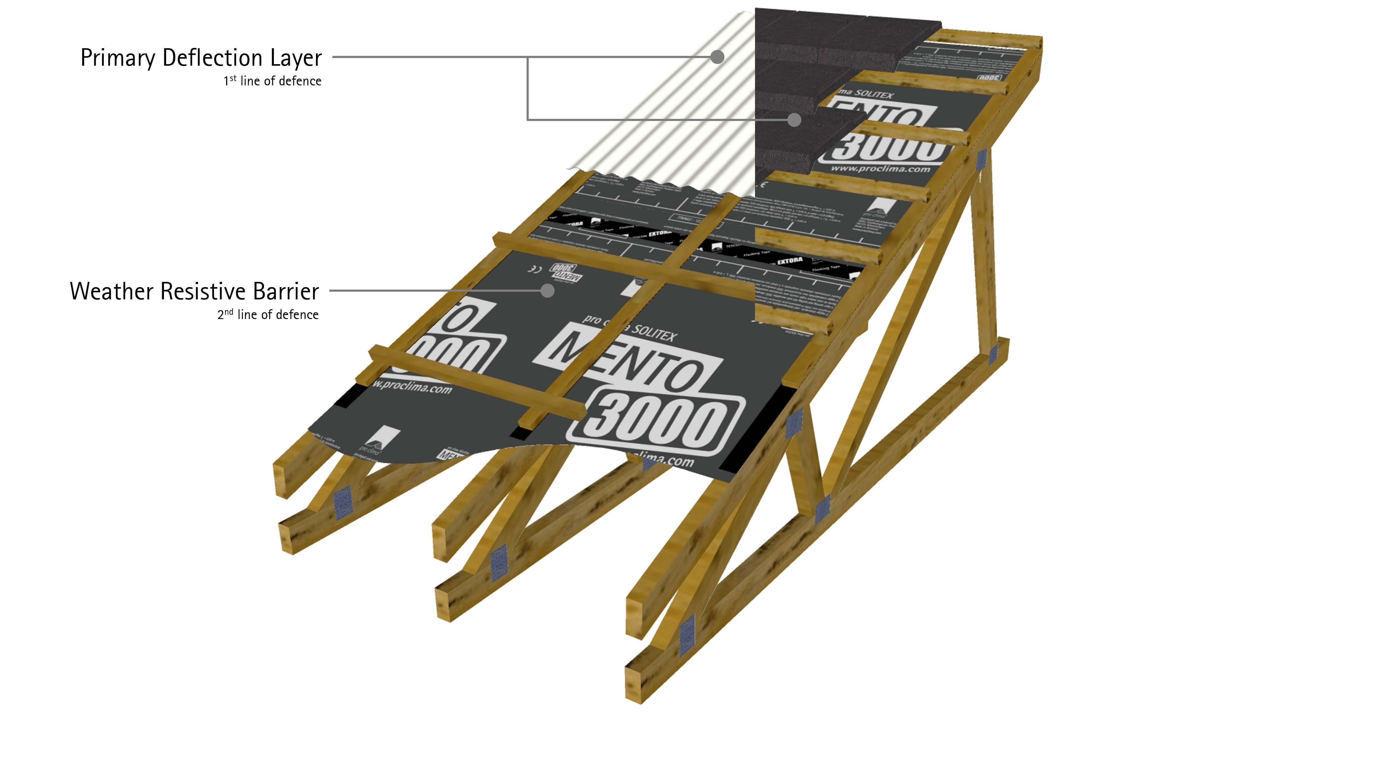
The combination of wind and rain at any given time is known as driving rain (Straube, 2010). Water being driven against the flow of gravity by wind should not be underestimated (Overton, 2013). Wind-driven rain must be accounted for in any roof design, whether it be continuous long-run metal or tile. A good cladding system is the first line of defence. Beneath this, a secondary line of defence is required and this should take the form of a Weather Resistive Barrier (WRB).
Extra-Terrestrial Effects Night-Sky Radiation
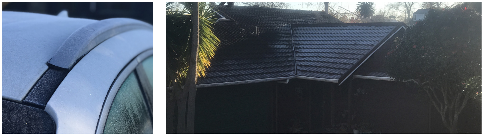
Night-sky radiation is a super powerful effect of outer space that can suck the energy out of our roof cladding. It can result in supercooling of the roof surface down as much as 10°C below ambient air temperature (Figure 5 & 7). Clouds have an insulating effect on the Earth’s surface, much like a big blanket. When the sky is clear, this blanket of insulation is effectively removed and longwave radiation is relatively free to emit energy back to space. The resulting net energy loss is most pronounced on surfaces facing the sky, such as roofs. It is most obvious at night time when the energy flowing out to space is not balanced by any solar radiation.

Water Vapour on the Inside
The human body is moist, made up of 50 – 70% of water depending on physiology, gender and age (Roland, 2019). Respiration and perspiration release water vapour from our bodies into our abode. Compounded by other routine activities, such as cooking, cleaning and bathing, we put plenty of water into the interior environment of our buildings.
Having water on the inside of our buildings in the wrong place or at the wrong time will cause problems because we are not the only residents of our blue planet that have evolved to make use of water.
Water makes things grow. From plants to humans, and everything in between, including fungus and mould. Life on planet Earth (and in our homes) relies on moisture to thrive. If you take moisture away, living organisms, such as mould, cannot grow. But in the presence of moisture, our buildings tend to provide good growing conditions for mould (Figure 10).
The roofing by which we protect ourselves needs to be designed to withstand the external forces of nature (wind, hail, snow, rain and humidity) while also not trapping water vapour from inside.
Material selection is important. Some manufactured board materials are extremely mould sensitive, particularly those containing cellulose, which mould likes to eat. If the moisture and the food sources are limited, then mould has less chance to thrive, but our buildings tend to have an abundance of cellulosic food. Timber and the paper backing of plasterboard all contain cellulose.
If we can’t remove the food, it’s even more important that we avoid and remove moisture.
Water in Between
Water on the outside of our buildings is relatively easy to protect against. With respect to roofs, deflection is the primary line of defence. This relies on the shape and integrity of the cladding material. Beneath the cladding, we implement drainage as a secondary line of defence against any liquid water that might get through the cladding, especially under severe driving rain conditions.
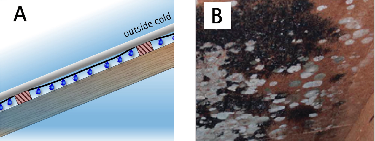
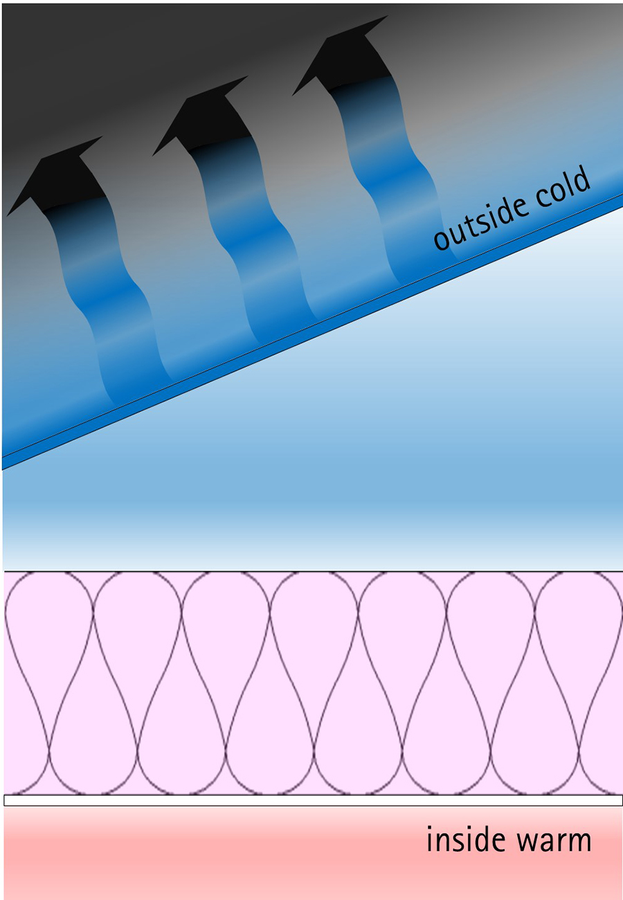
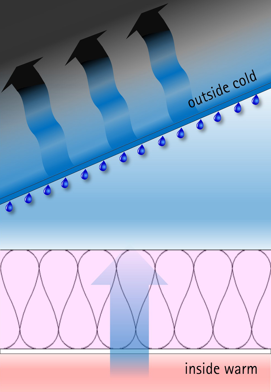
Water vapour on the inside of buildings is theoretically easy to manage with extractor fans and good ventilation. Unfortunately, most Australian and New Zealand homes don’t manage internal humidity very well. This makes for unhealthy indoor living conditions and adds a potential moisture load to the roof structure of the building. If this moisture is allowed to reach the cold surface beneath the roof cladding, it is likely to condense into liquid water causing a mini rain shower inside the roof assembly (Figure 11 – 16).
The moisture in between the inside linings and outside cladding of our buildings can pose the biggest risk. This interstitial moisture is a problem because:
- Prolonged moisture in the structure can cause a lot of damage.
- Mould growth facilitated by moisture can affect the health of the building occupants.
- In a lined and clad house, interstitial moisture is invisible.
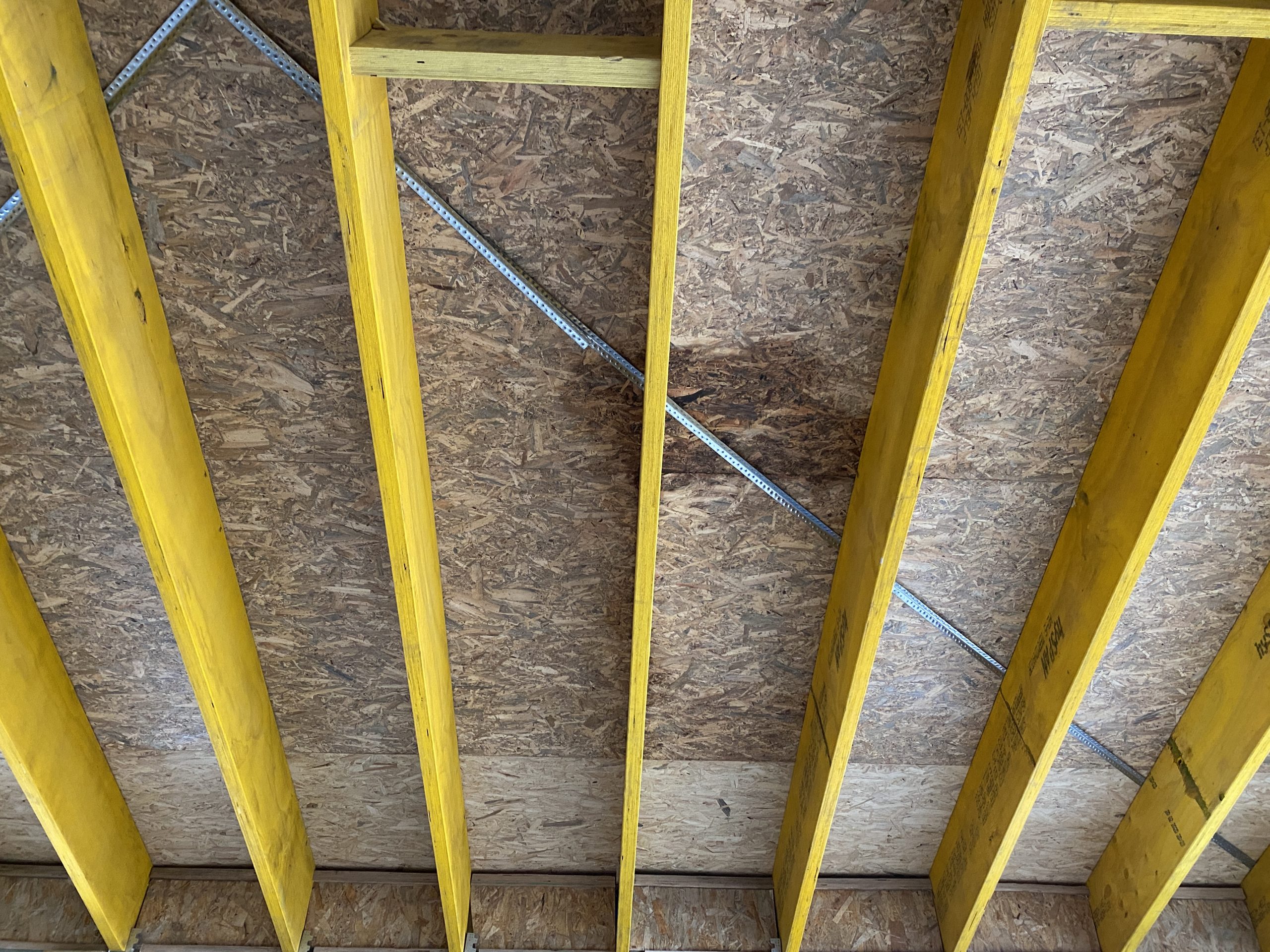
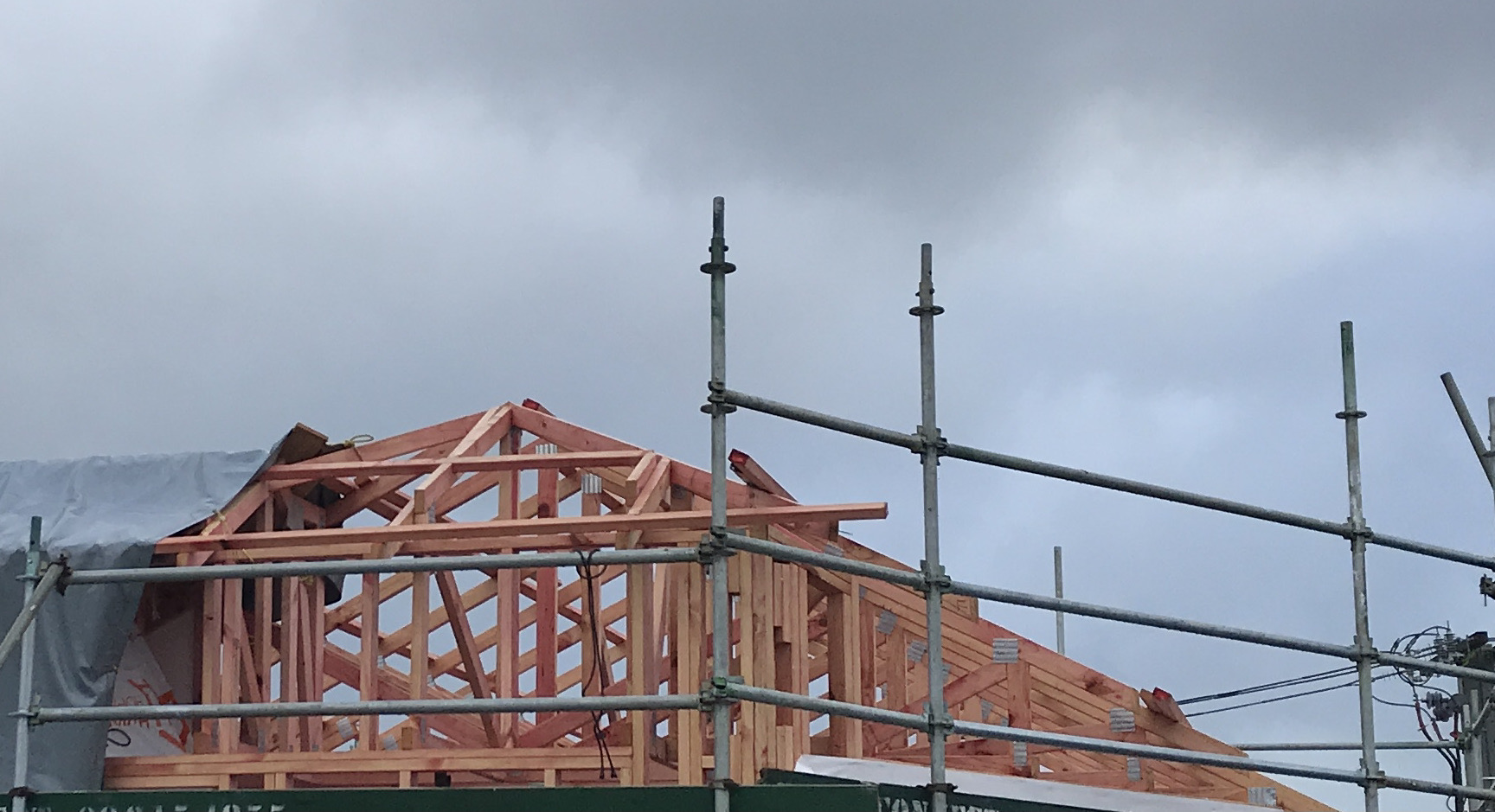
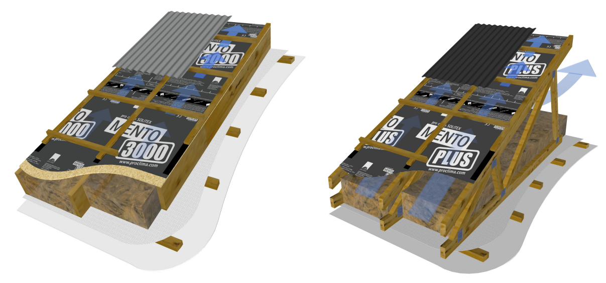
Truss Roofs
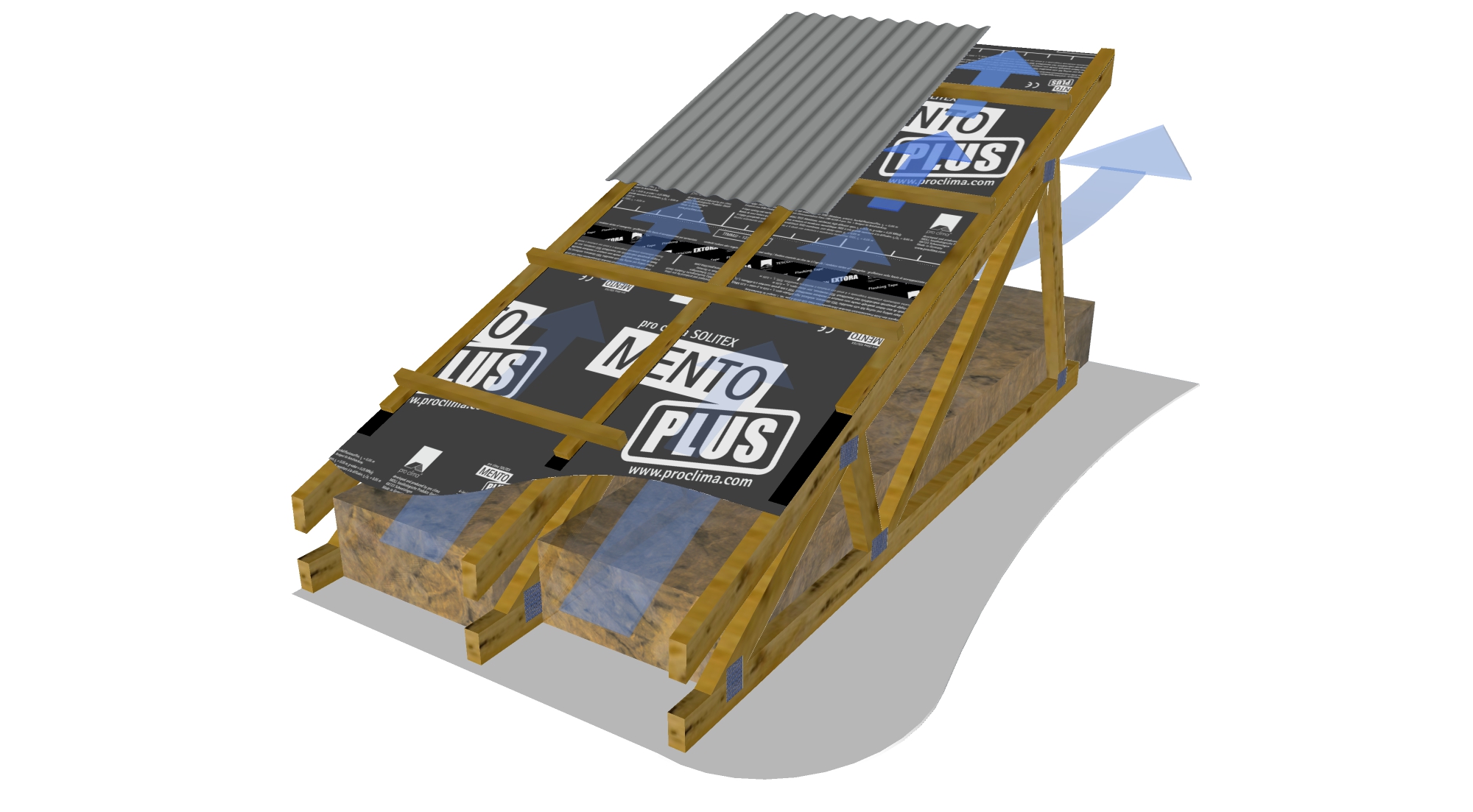
Skillion Roofs
Pressure, Pores and Perforations
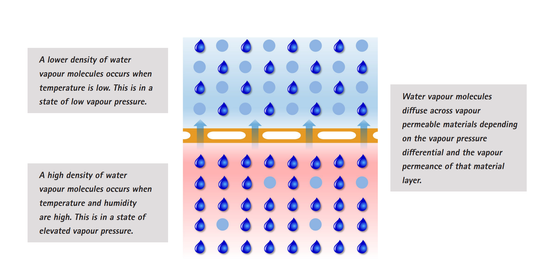
There are many mechanisms by which air and water vapour can move through walls, roofs and floors to increase interstitial moisture. Vapour pressure is one such mechanism. The pressure of water vapour on one side of any boundary is relative to the density of water vapour molecules suspended in the air. A difference in vapour pressure will cause moisture to move in one direction or the other. We describe this pressure difference as a gradient.
We’re very familiar with the force of gravity pushing an object down a physical gradient. Think of a ball on a see-saw. When the see-saw tips, the ball will roll downhill. If the see-saw tips back again, a gradient is created in the opposite direction and the ball will roll back to its original position.
We’re also pretty familiar with the concept of gradients when it comes to heat and wind. Heat energy always travels from a warm source to a cold source. Wind is air moving from a place of high air pressure to a place of low air pressure.
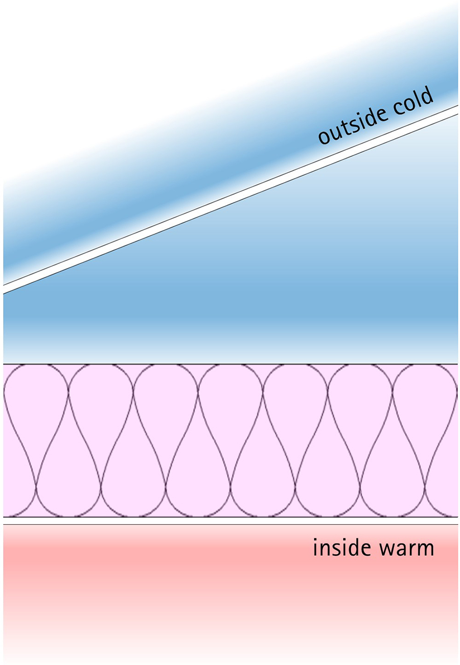
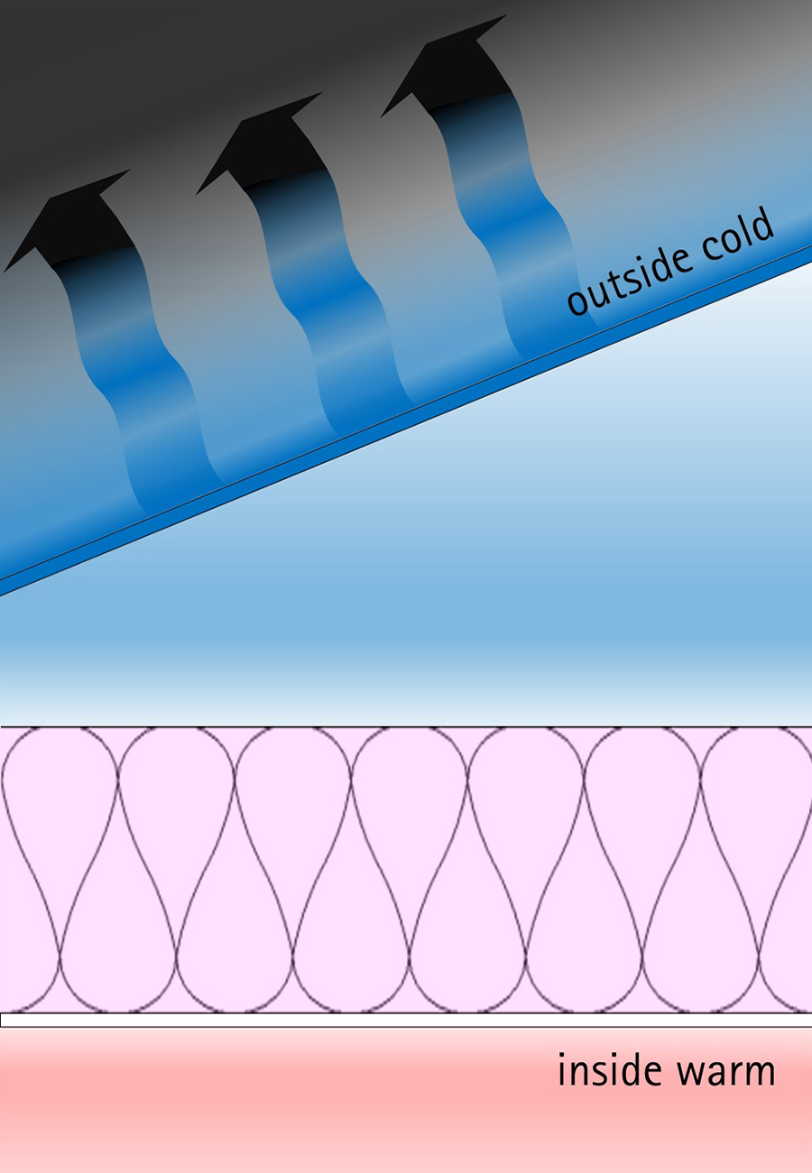
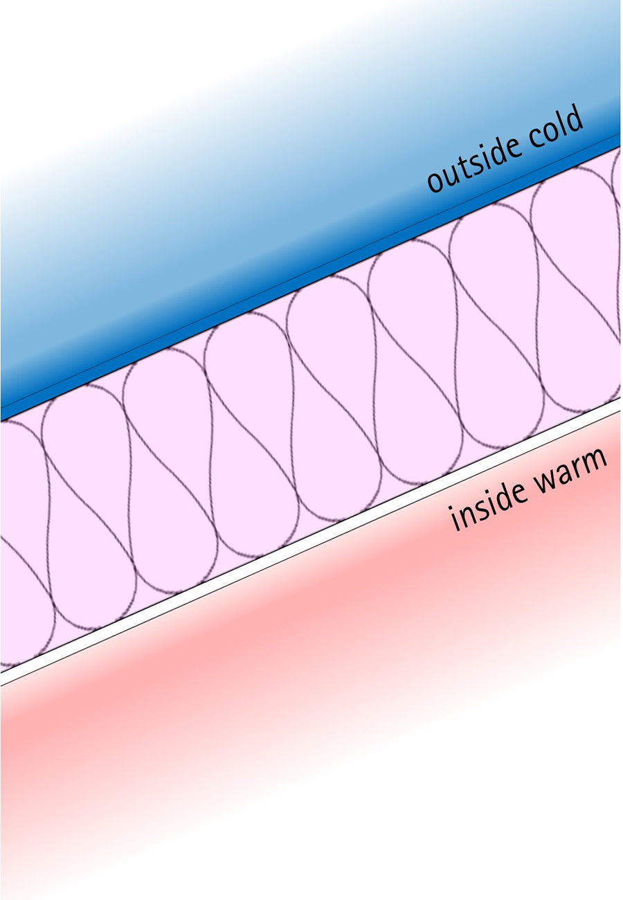
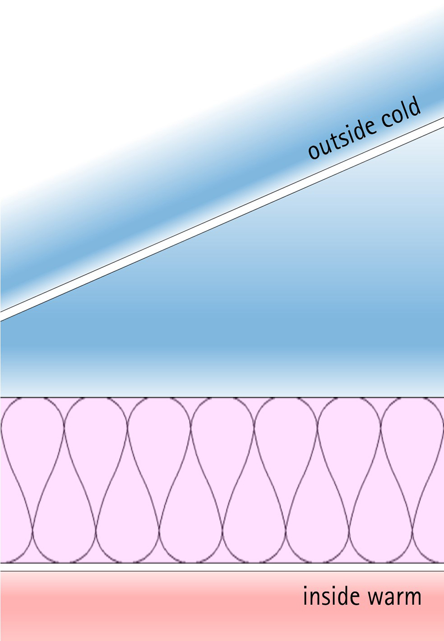
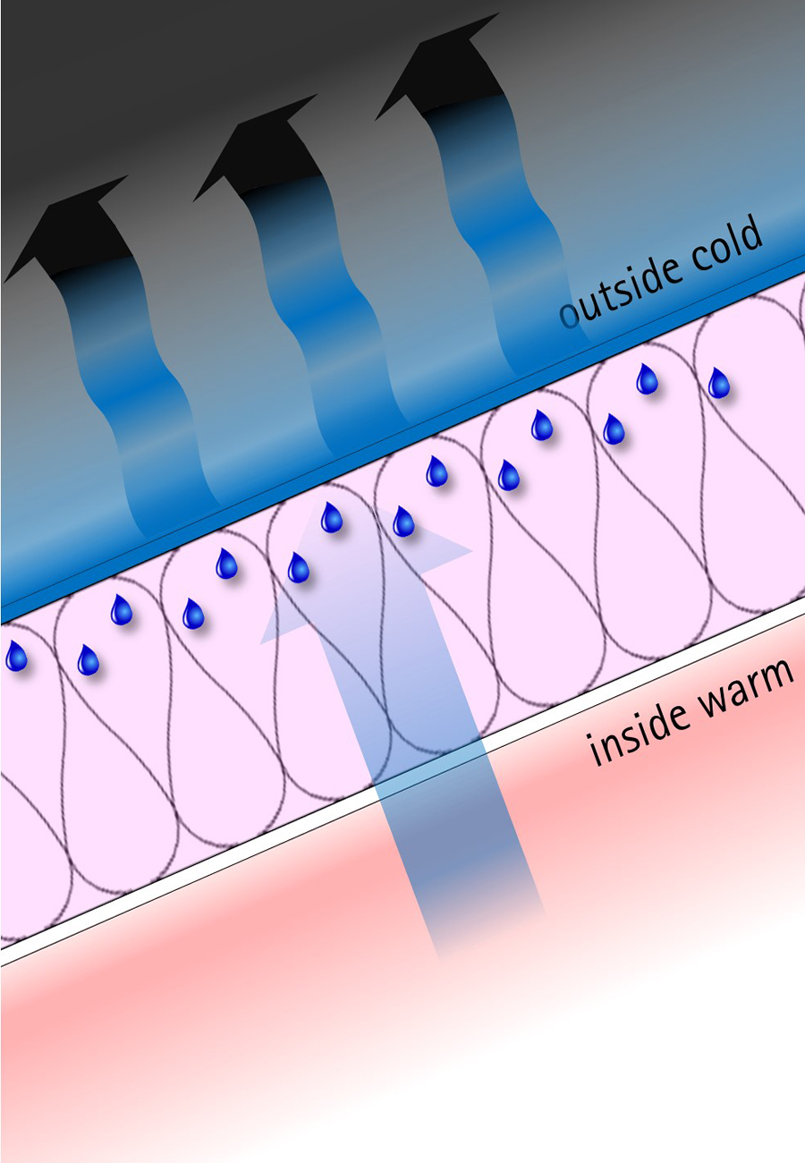
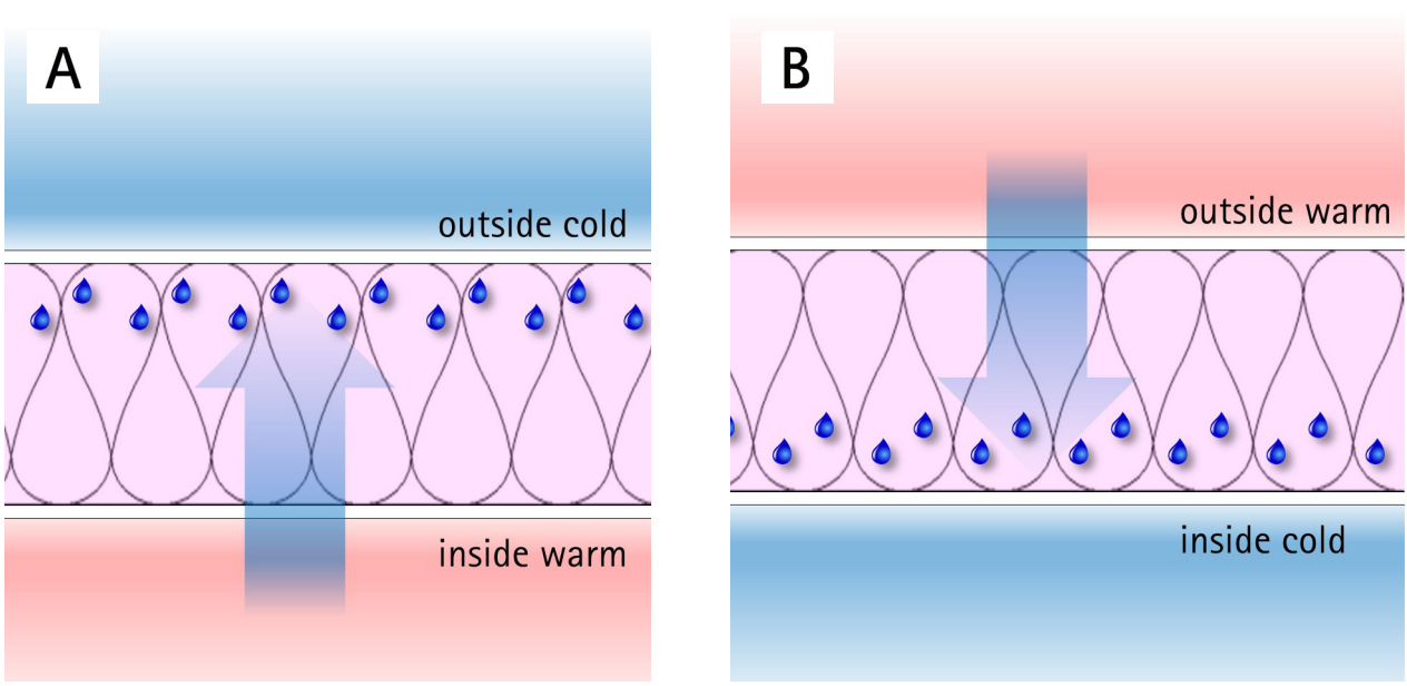
Vapour pressure follows the same laws. Moisture in the form of vapour will always travel from a place of high vapour pressure to a place of low vapour pressure. Because warm air can hold more moisture than cold air, the warmer side of our building envelope usually has a higher vapour pressure than the colder side.
Therefore, in winter and during the night, the vapour pressure gradient is such that moisture from the inside of our buildings is pushing through the envelope to get to a place of lower vapour pressure on the outside and vice versa in humid summer conditions (Figure 17).
Greater Gradients
Moisture within the structure of our buildings has become more of an issue in the last few decades because we’ve increased the pressure gradient. We have effectively tipped the see-saw higher.
When our buildings were full of gaps and holes, then air, moisture and heat were relatively free to move in and out. This was uncomfortable, so we added insulation which increased the temperature gradient.
Building materials and practices have also created more sealed envelopes. This is a good thing when it is done with intention and with consideration for vapour control (discussed later), but if air sealing is done accidentally, in the wrong position and without allowing vapour to move out of the envelope, we end up with problems (Figure 18).
Heat and Moisture in Motion
Weather on the outside and human activity on the inside move heat, moisture and air, all of which can then move through the structure of our buildings.
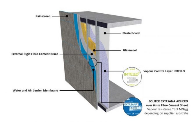
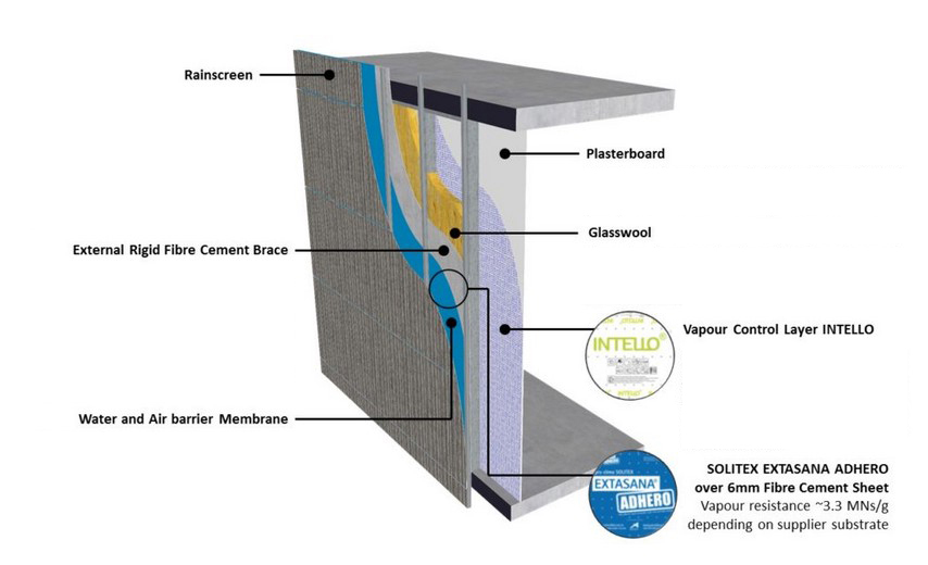
- Vapour diffuses through all permeable construction materials, e.g. plasterboard, roofing membranes (Figure 19).
- Liquid is transported through all porous construction materials, e.g. timber.
- Air moves by convection through and within cavities, including ventilation cavities between the roof cladding and substrates.
- Vapour travels within the air, through unintentional gaps and cracks, particularly through ceiling penetrations.
- Moisture can be stored in most roof construction materials such as absorbent membranes, timber and insulation material.
- Heat radiates between materials and to the sky.
- Heat conducts between materials and air layers.
All these forms of energy and mass transfer need to be considered when analysing the drying potential of a roofing system. We can do this using computational hygrothermal tools such as WUFI® to look at the combination of heat and moisture movement through all the materials that make up a roof system.
When we understand these flows and design appropriately, we can create a roof system that responds predictably to the known forces of physics.
AUS – wufi.com.au/professionals/
NZ – wufi.co.nz/professionals.
The Water Vapour Superhighway
Counterintuitively, adding water vapour to air actually makes that body of air lighter. Moist air is less dense and therefore more buoyant than dry air because water vapour molecules are lighter than the nitrogen and oxygen molecules that dominate the air. The small size of water vapour molecules also allows them to travel where water and even air cannot (Australian Building Codes Board, 2019).
Interstitial moisture accumulates when we construct roofs in a way that allows moisture to only go part of the way through the building envelope before it gets blocked. Large holes such as unsealed gaps and small holes such as intentional perforations in non-permeable materials are examples of such pathways for moisture-laden air.
Warm humid air wants to go upwards and it will find gaps and cracks in the ceiling linings.
“The ceiling contains gaps, such as around loft hatches and service penetrations, which provide routes for air to flow from the occupied space into the loft [attic/roof space]. There are also more complex airflow routes; for example, through wall cavities and behind lining systems. Heat and moisture are generated by the normal activities of the household within the occupied space of the house below the ceiling, raising the temperature and vapour pressure above the ambient conditions outside. Some of this heat and moisture leave the living areas of the house, passing through the ceiling into the loft [attic/ roof space] by a combination of conduction, diffusion, and air movement. This movement contributes significantly to heat loss from the house and leads to a risk of condensation within the loft [attic/roof space]. Reducing the airflow through the ceiling as far as is practicable will both save energy and reduce the risk of condensation.” (Sanders & Rideout, 2006)
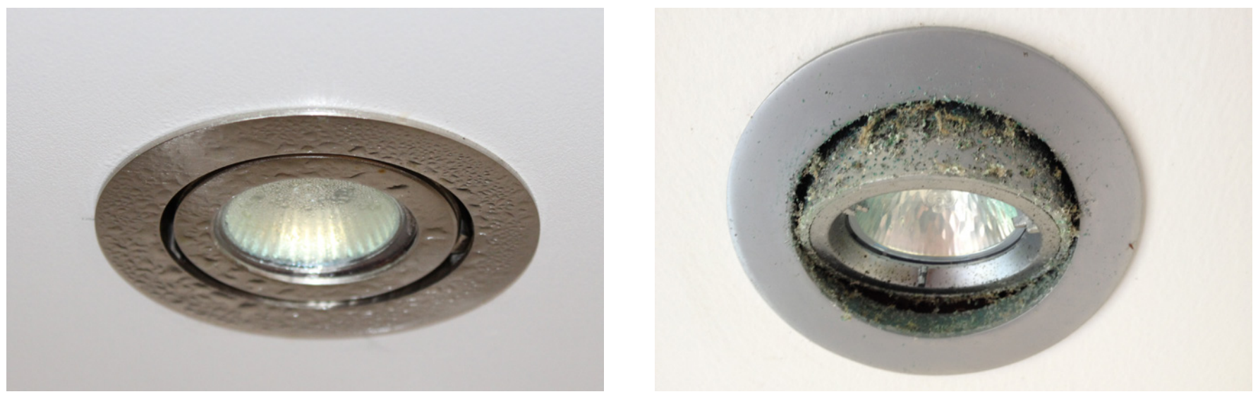
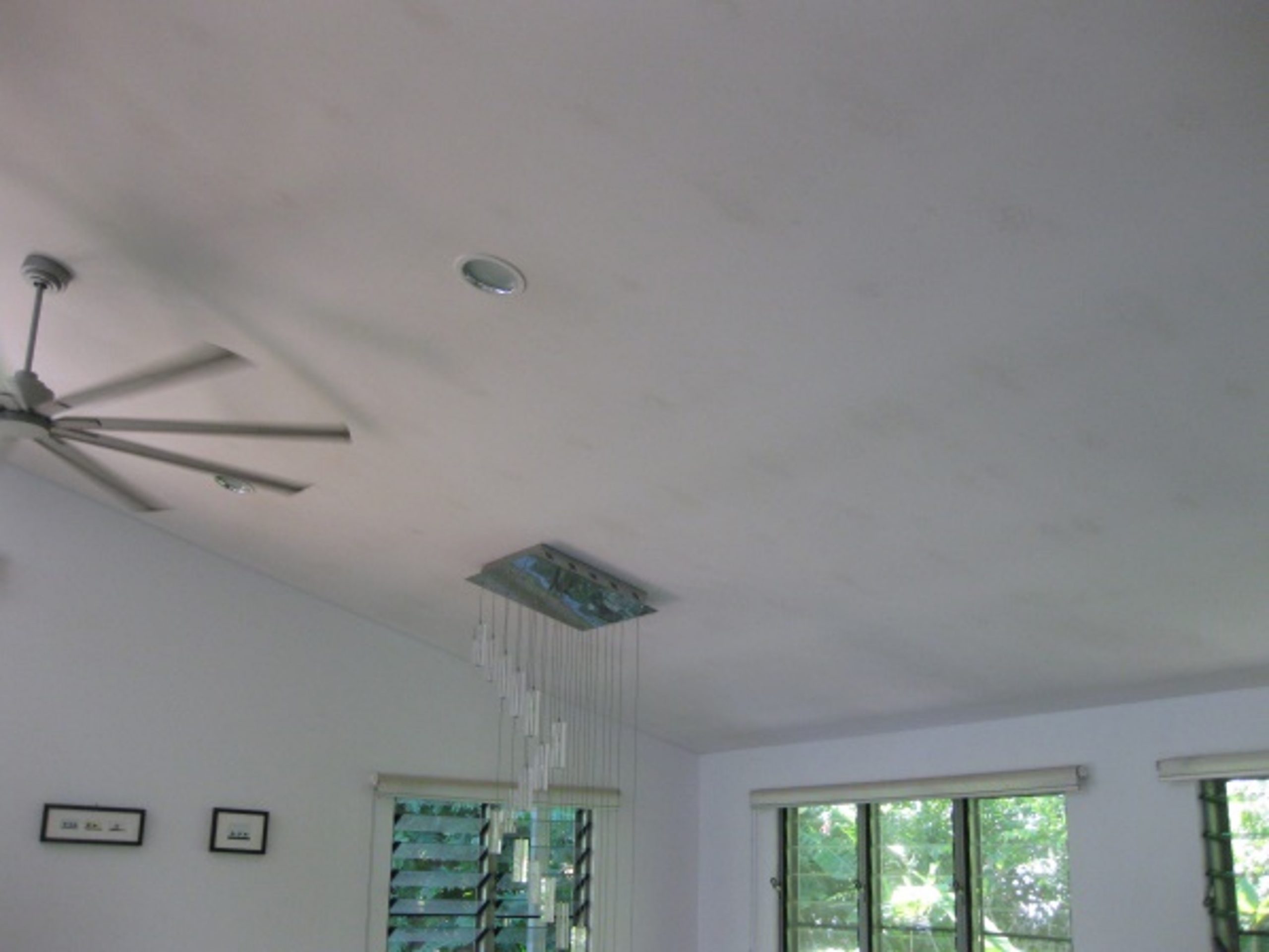
Ceiling penetrations for lights, vents, speakers and other services are basically unavoidable. A properly designed and dedicated Intelligent Air Barrier (IAB) above these services can achieve heroic outcomes by controlling the flow of vapour.
Ventilation – Countering Counter Radiation
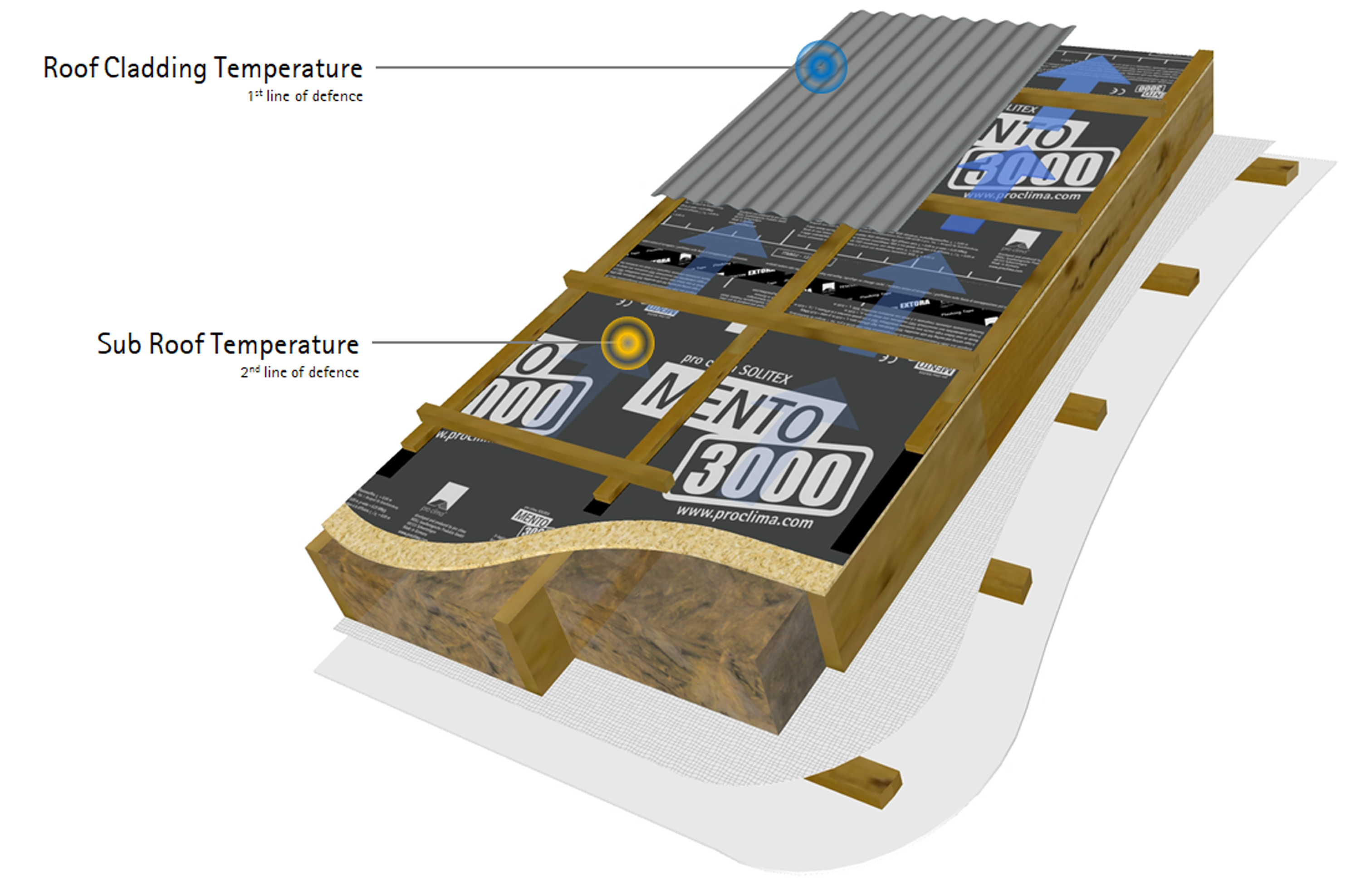
The force is strong with night-sky radiation. Despite many climate regions in Australia and New Zealand not being “cold” by international standards we need to consider the fact that the actual roof cladding temperature could be at least 10°C cooler than the minimum reported air temperature. This completely changes the way we need to consider our roofs. We cannot stop night sky radiation from cooling the roof surface. All we can do is design to manage its effect.
“The surface temperature of the sub-roof beneath the ventilation layer and the tiles is one of the most important factors for the hygrothermal performance of pitched roofs. The air layer between tiles and sub-roof and the air exchange with the outdoor air influence the heat transfer and therefore affect the moisture level inside the roof construction.” (Philipp Kölsch, Fraunhofer IBP, 2019)
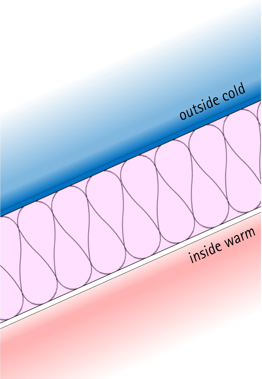
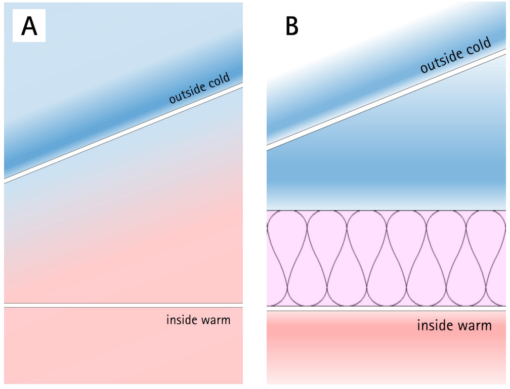
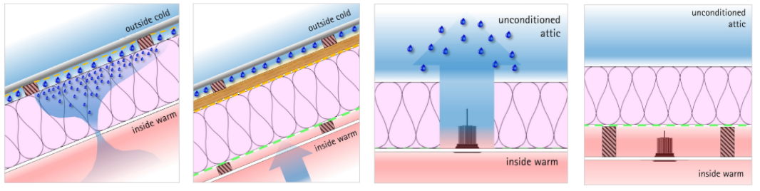
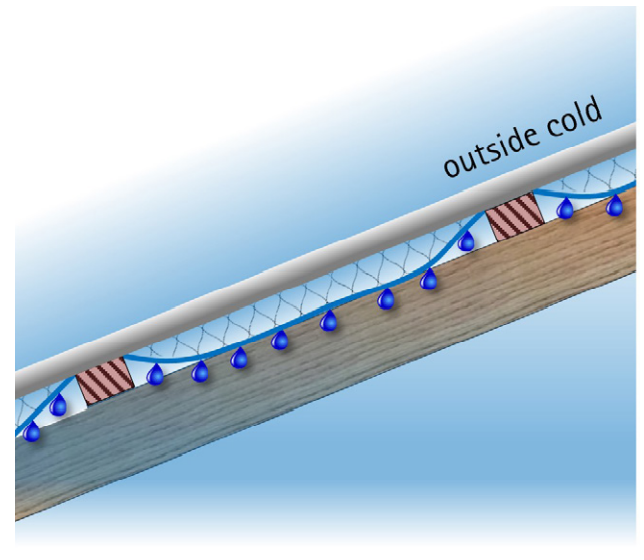
In winter and at night, the coldest surface in a roof assembly will be the cladding. However, it can also act as a radiant shield to protect the roofing layers below from excessive overcooling from the powerful effect of night-sky radiation.
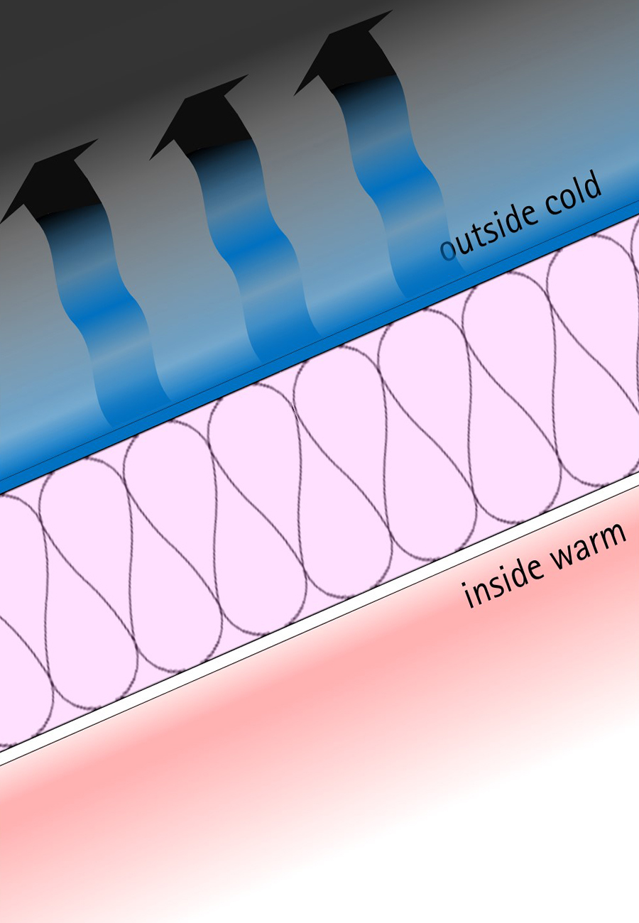
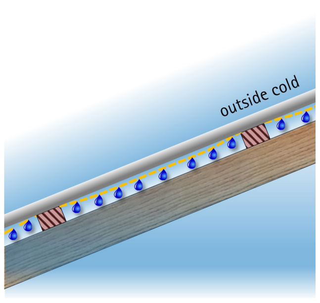
By separating the membrane from the cladding, ambient air is introduced between the first and second lines of defence. While we might still call this night-time air ‘cold’, it’s not as cold as the cladding which has been supercooled by night sky radiation. Therefore the ambient air will have a slight but significant warming effect on the roof cladding and underlay (Figure 22).
“During night-time, the long-wave radiation losses mainly affect the cladding and lead to a notable overcooling below the outdoor air temperature, while the surface temperature of the sub-roof remains close to the outdoor air temperature.” (Kölsch, 2019)
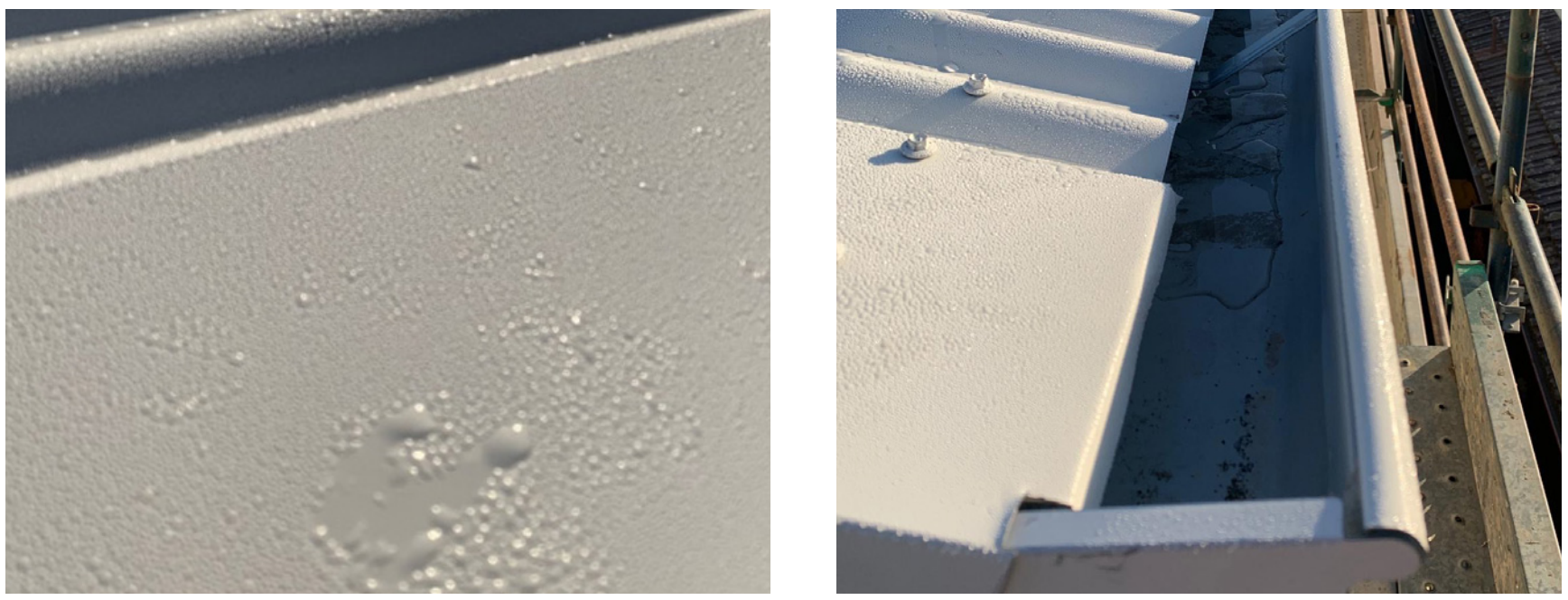
Water Vapour and Cold Surfaces
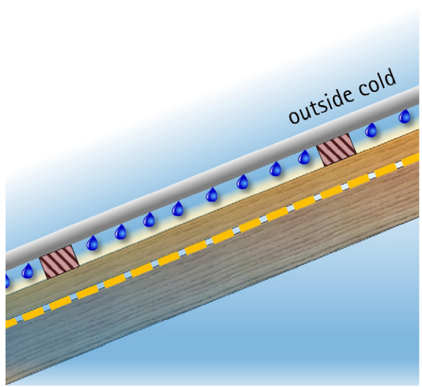
Water vapour will readily condense onto cold surfaces, or within the pores of cold materials, resulting in increased material moisture content. If these cold surfaces and materials are located towards the outer (cold) side of the roofing system, there is a risk of mould growth and timber rot because the high moisture content levels are likely to be sustained. To avoid this, a drainage path for condensate is mandatory, not optional.
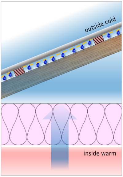
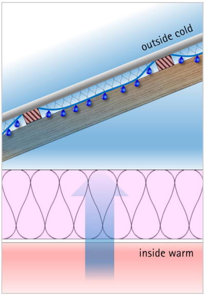
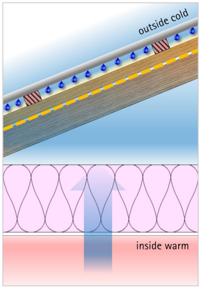
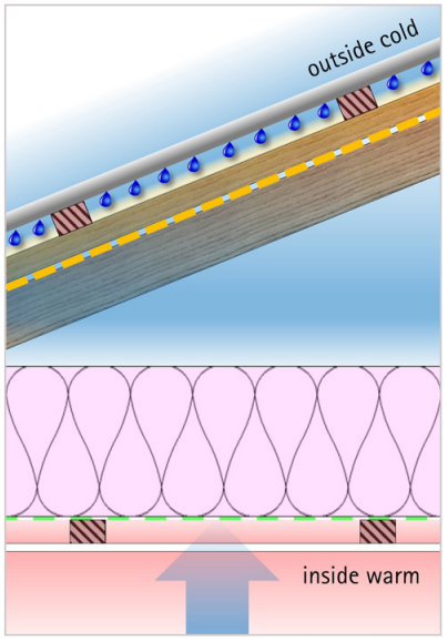
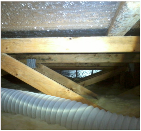
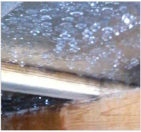
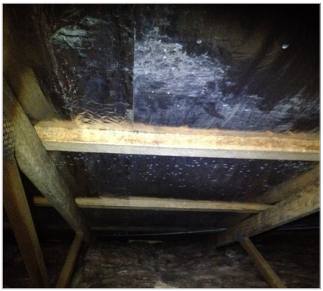
Figure 30: Moisture related issues on aluminium foil condensing surfaces. Photos courtesy: Dewsbury, Law, and Henderson, 2016.
Building Physics Reversed
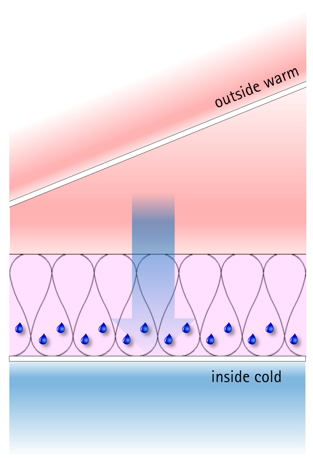
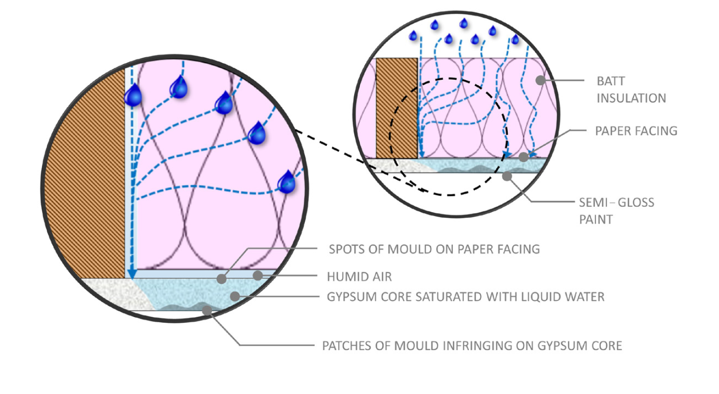
The rules of physics cannot be broken but the forces may reverse. Seasonally this can drive water vapour pressures the other way meaning that the plasterboard adjacent to air-conditioned environments becomes the cold surface. This is a particular issue in humid and tropical climates where air transported water vapour and diffusion processes may result in the attraction of water vapour to internal cold plasterboard layers covered in cellulose paper facings. The resulting moist, warm environment with an abundant food source is perfect for mould growth (Figure 31 – 33).
External Humidity
Attic Space – Controlling the Uncontrollable
In truss roof systems there is a large air void. In most cases, it is prudent to ventilate any large air voids on the outside of the insulation layer. This is because large air voids are unpredictable. Water vapour will readily be re-distributed to the coldest places in the assembly.
The mighty truss still dominates in Australia and New Zealand and is not going anywhere anytime soon. The best we can do is to remove as much moisture as possible within the large air void via ventilation. A roof ventilation strategy needs careful consideration:
“Because the primary purpose of ventilating roofs is to remove moisture, the design and location in the roof should obviously allow for good airflow. Outlet vents, such as ridge vents, must only be installed in conjunction with inlet vents. Inlet vents should be dimensioned slightly larger than the outlets to ensure all makeup air comes from outside and is not drawn from inside the building. “ (BRANZ, 2018)
The key to ventilating a roof is having sufficient opening area to allow air into the attic space. There are various thresholds internationally. For guidance, an open area ratio of 1:300 implies 1m2 of vent opening area is required for every 300 m2 of the insulated ceiling.
“The size of the ventilation is often described as a ratio between the net free opening area of the vents to the area of the insulated ceiling. While ratios ranging from 1:150 to 1:600 can be found, 1:300 seems to be a frequently specified fraction. “ (BRANZ, 2018)
Construction Process – Temporary Protection
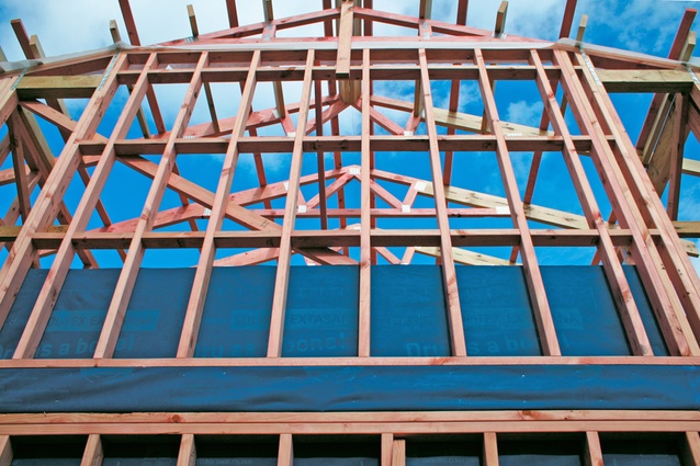
When constructing a roof with ASV, the battens and cladding may be installed at different times. Therefore, there is a risky period where the Weather Resistive Barrier (WRB) may get rained on. In this situation, it is necessary to have good seals on all penetrations (Figure 35).
There is moisture within the structure of buildings to begin with, especially in brand new buildings. Trusses and rafters are supposed to be dry but it’s never completely dry (20% moisture content, by definition, means that at least 20% by mass is water), and timber is often allowed to get saturated before buildings are properly closed in (Figure 36).
Other materials like concrete are also massive sources of moisture for new buildings. If the ceiling is not completely sealed, then these moisture sources will contribute to the moisture load of the roof. Even in the best case scenario, where the framing and materials are kept ‘dry’ during construction, moisture will always be trying to get in. We, therefore, need to be designing roofs that allow for drying.
Above Sheathing Ventilation (ASV)
Above Sheathing (Membrane) Ventilation allows us to fight mould, timber rot and corrosion by protecting against the exterior weather while increasing the drying potential. When designed and constructed well, ASV will help maintain a durable and healthy building.
Properly implemented ASV improves durability and comfort by:
- allowing the structure to remain dry during construction,
- preventing water leaks in extreme weather events during operation,
- preventing the accumulation of internal water vapour in the structure during normal operation and
- reducing excess heat load from the sun (ASV – Part 3: Fighting The Sun).
Living with Water
Without water people die. Without moisture, mould and timber destroying fungi cannot thrive. Keeping water out of the building envelope and increasing the drying potential is a simple formula, in theory. In practice, the secret to a dry, durable roof is to have specific ventilation in a specific location for a specific purpose. The best place for controlled contained ventilation is between the cladding and the membrane.
Buildings are not submarines. We should design and construct our buildings with an understanding of how water, vapour, air and heat will move in, around and through the building enclosure. When we understand and apply the laws of physics, we can successfully construct safe, healthy places to enjoy our blue planet in comfort.
ASV facilitates drying of the roof by using similar physics that creates rising clouds on the surface of the Earth. A layer of moisture-laden air underneath the roof cladding is warmed by the morning sun on the roof. This buoyant air moves up the cavity towards the ridge and is replaced at the eave by cooler air. If any liquid water does accumulate on, or leak into the underside of the roof cladding, drainage is facilitated in ASV by the unimpeded pathway on top of the roof membrane. Meanwhile, moisture vapour is carried out of the system by the moving air. In this way, ASV does not rely so much on diurnal absorption and desorption of moisture by the roofing underlay. As discussed in ASV – Part 1: Rise of the Cavity, this continual wetting and drying is really only dealing with the symptom and will likely cause rapid degradation of the underlay.
Water and Heat
This article has covered the impact of water from the outside, the inside and within our buildings. We are wet beings living on a wet planet, but we want our buildings to be as dry as possible in order to be durable and to provide healthy places to live, work and play. ASV is a method of constructing roofs to keep the structure dry using proven building physics.
The next instalment of the series will look at the summer cooling benefits of ASV and how including the right type of ventilation in the right place can help make our buildings more comfortable and energy-efficient.
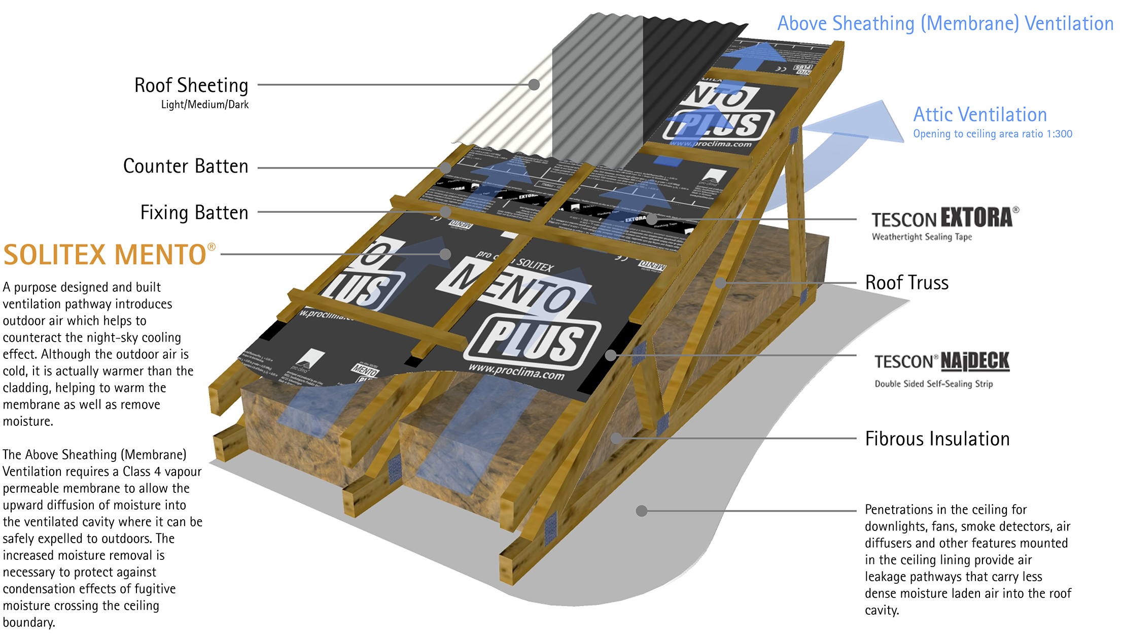
Figure 38: Solution 1 – ASV provides optimum moisture management at the roofline. Ventilation of the attic is always recommended at a ratio of at least 1m2 of the opening area for every 300 m2 of the insulated ceiling (BRANZ, NZBC, BCA) unless specialist advise has been sought.
Remove moisture using a designed ventilation cavity. Counterintuitively, the cold winter air entering the cavity at a low level is warmer than the cladding which is exposed to night-sky radiation. The ventilation, therefore, helps to warm the membrane, reducing the risk of moisture damage and reducing the overall heat loss.
The arge attic void should always be ventilated with a ratio of 1m2 of ventilation for every 300 m2 of ceiling area unless a specialist hygrothermal expert advises otherwise. Inlet vents should be dimensioned slightly larger than the outlets to ensure all makeup air comes from outside and is not drawn from the inside the of building.
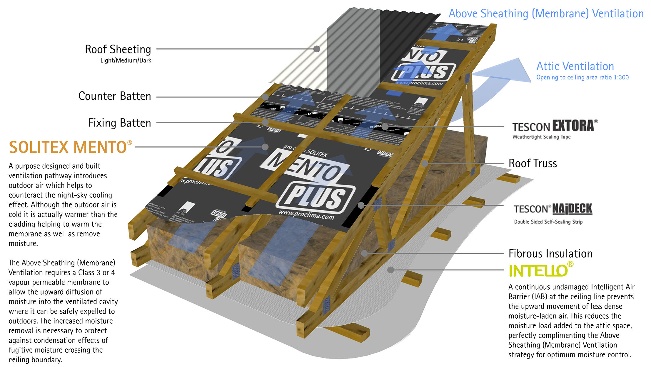
Figure 39: Solution 2 – INTELLO® or INTELLO® PLUS Intelligent Air Barrier system at the ceiling line, coupled with a services cavity, allows a continuous and undamaged vapour control layer which limits the upward movement of interior air into the roof space. This reduces the moisture entering the roof space, assisting the ASV strategy to keep your roof dry. The large attic void should always be ventilated unless a specialist hygrothermal expert advises otherwise. The risk of a thermosyphon effect drawing moisture-laden air from the living space is eliminated in this system.
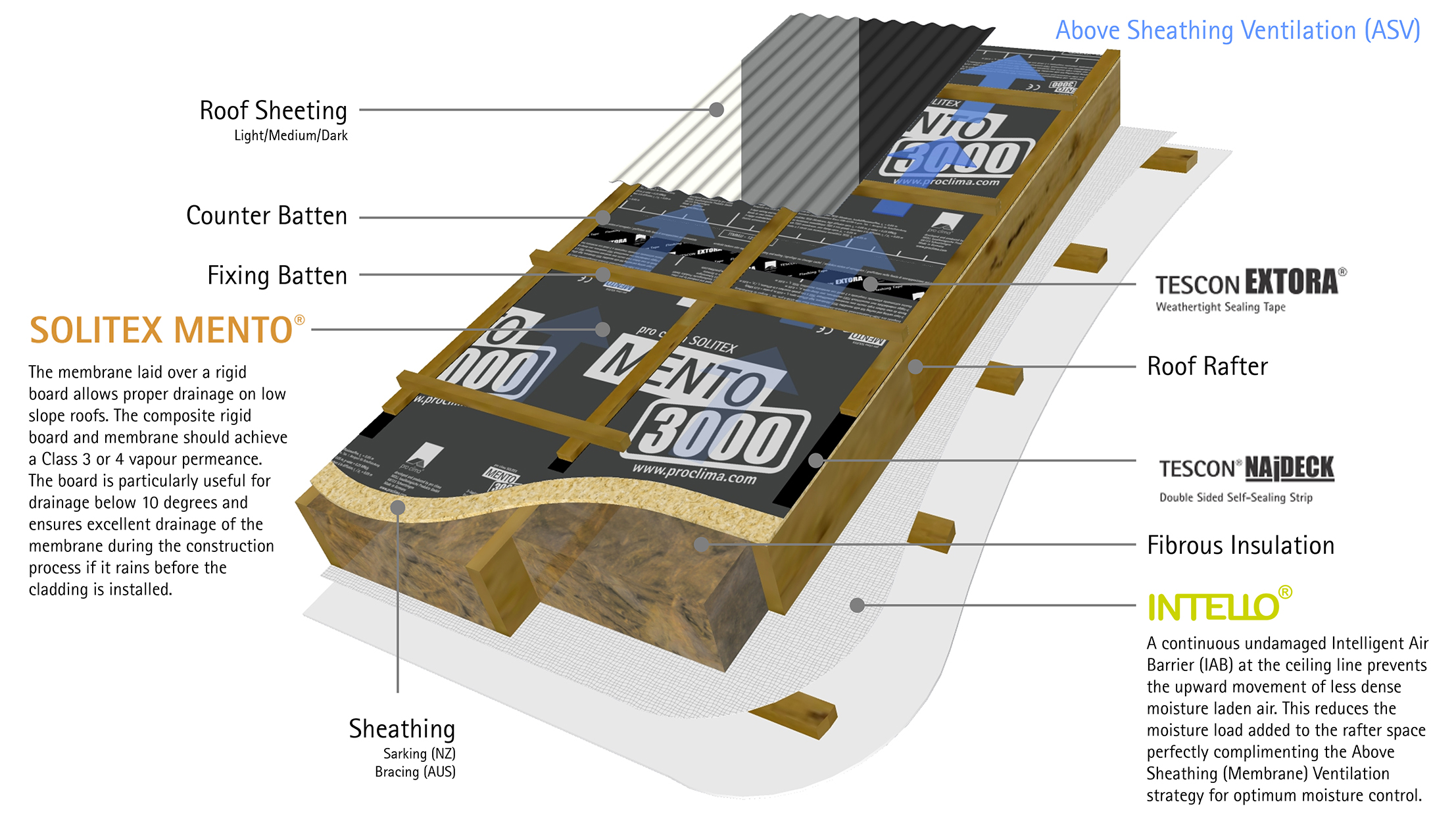
Figure 40: Solution 3 – Removing the large air void inherent in rafter roof design means the thermal and moisture characteristics of these roof systems are highly predictable. This means that with the right professional advice, you can rest assured your roof will work as you intended.
REFERENCES:
1. BRANZ. 2018. Roof space ventilation in New Zealand houses. Building Research Association of New Zealand. (Roof ventilation #1)
2. BS 5250:2011+ A1:2016. Code of practice for control of condensation in buildings. British Standards Institution.
3. Commonwealth of Australia and States and Territories of Australia. 2019. Handbook: Condensation in buildings. Australian Building Codes Board.
4. Dewsbury, M., Law, T., and Henderson, A. 2016. Investigation of Destructive Condensation in Australian Cool Temperate Buildings. School of Architecture and Design & School of Engineering, University of Tasmania.
5. Dhaenens, C. 2018. [Online]. Unsplash.
Available: https://unsplash.com/photos/Zz_3R91RQyo. [June 2021].
6. Kölsch, P. 2019. Hygrothermal Simulation of Ventilated Pitched Roofs with Effective Transfer Parameters. Fraunhofer Institute for Building Physics IBP.
Available: https://wufi.de/en/wp-content/uploads/sites/11/2015/11/WUFI-Pro_Ventilated-pitched-roofs.pdf
7. NASA/JPL. 1996. Photojournal. [Online]. NASA Jet Propulsion Laboratory California Institute of Technology.
Available: http://photojournal.jpl.nasa.gov/catalog/PIA00122. [June 2021].
8. Overton, G. 2013. An Analysis of Wind-Driven Rain in New Zealand, Study Report SR 300, BRANZ.
Available: https://d39d3mj7qio96p.cloudfront.net/media/documents/BRANZFacts-Roof-ventilation-1-NZ-roofs.pdf
9. Roland, J. 2019. What Is the Average (and Ideal) Percentage of Water in Your Body? [Online]. Healthline Media.
Available: https://www.healthline.com/health/body-water#percentage#body-water-charts [June 2021].
10. Sanders, C., & Rideout, N. 2006. Airtightness of Ceilings: Energy Loss and Condensation Risk. BREPress
11. Straube, J. 2010. Simplified Prediction of Driving Rain on Buildings: ASHRAE 160P and WUFI 4.0, Building Science Corporation.
