
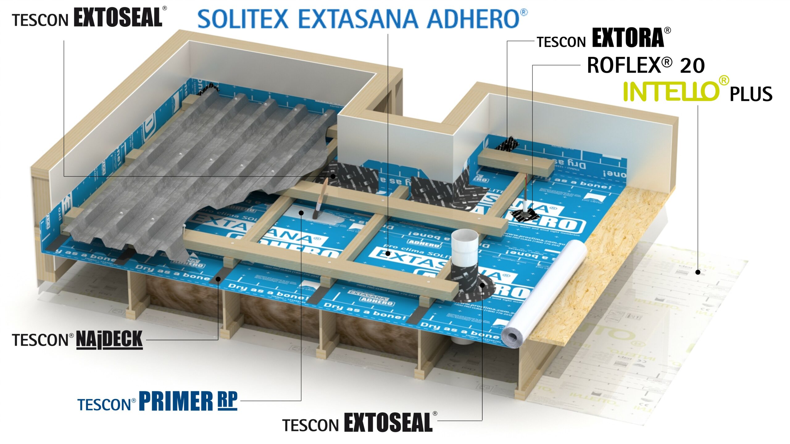
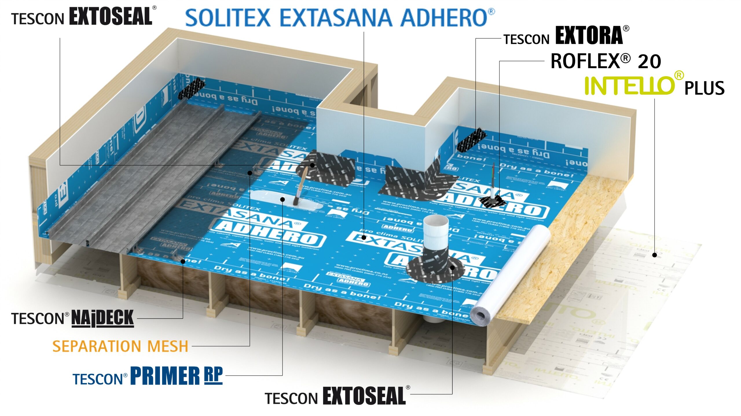
Above Sheathing Ventilation – Part 0: Flat Roofs

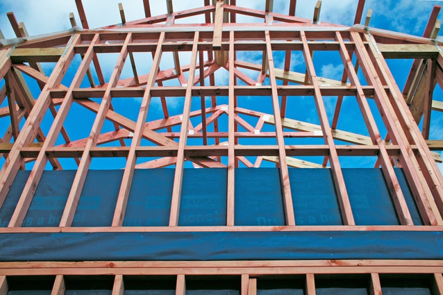
What’s a Ventilated Flat Roof?
It is a low-pitched roof (≤10º) with an additional ventilated cavity space below the roof cladding. According to our European colleagues, it provides the opportunity to implement a diffusion open/permeable layer on the outer side of the insulation layer. This creates drying capacity for the construction in two directions, to the interior and to the outside, improving the durability of the construction.
In Austria (ÖNORM B 3691), it is a requirement to install the “sub-roof” construction with a weathertight layer in addition to the roof cladding as with a separate draining pathway and gutter, or drip edge. Testing through the Holzforschung Austria (Timber Research Austria, HFA) showed that condensate will occur because of temperature gradients, where parts of the construction fall below the localized dewpoint. Therefore, a separate weathertight construction is strongly recommended. This effect is also evident on roofs in Australia and New Zealand (ASV Part 2) due to the radiative cooling effect on the cladding at night.
Why should an additional ventilated cavity be introduced and why is it necessary that a sufficient air change rate is required?
There are several ways that moisture and liquid water can get into the roof cavity.
- Diffusion moisture transport from the internal environment towards the external, which is usually only a small contributor.
- A more significant contributor to cavity moisture is convective air transported moisture through gaps in the building envelope.
- An underestimated contributor is humidity that can condense as a result of temperature differentials (e.g. radiative night cooling surfaces to below dewpoint, ASV Part 2).
- Sometimes the moisture loads come from construction materials, such as timbers, that have been enclosed with high moisture content above.
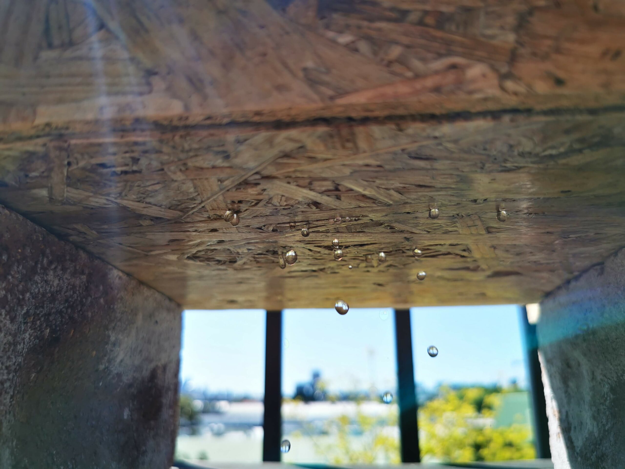
- During the lifetime of the roof, water can also enter the construction in the form of driving rain, ice buildup, or snow. Liquid water can drain if the construction is sufficiently sloped to allow for direct runoff. Small amounts of water can be absorbed and do not cause problems in the construction materials, however, accumulated moisture requires increased drying capacity for which ventilation is imperative. The higher the air change rate in the cavity, the greater the drying capacity.
- Drying capacity by diffusion processes can be calculated using advanced simulation tools such as WUFI® software developed by the Fraunhofer Institute for Building Physics which takes into account water vapour diffusion, built-in moisture and material properties to allow for drying.
Air movement can be achieved through thermal buoyancy (chimney effect), influenced by prevailing winds. The Holz Forschung Austria (HFA) collected data from research using an outdoor exposed low pitched roof structure allowing for wind impact compared against controlled laboratory test apparatus.
Thermal Buoyancy
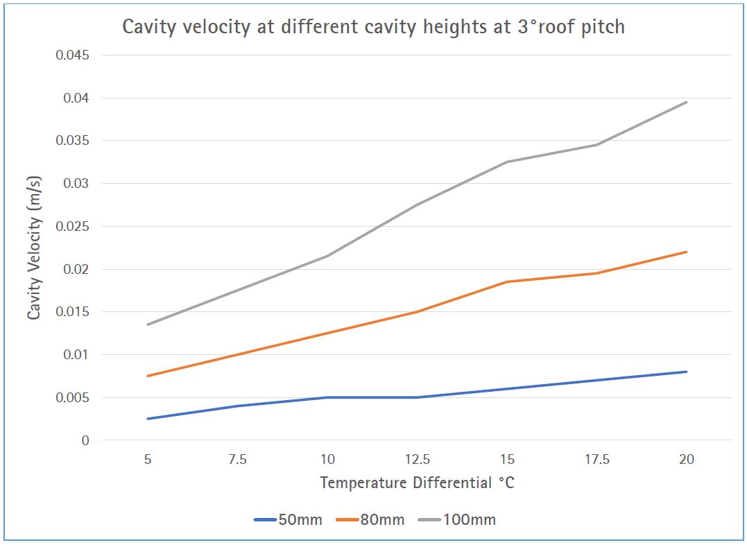
The laboratory tests measured the air velocity of a 10m long air cavity at different roof pitches, purlin heights (cavity height), ridge detailing, eave detailing and inlet/outlet differential temperature gradients as shown in figures 1 to 4:
• Temperature gradients in °C: Δ4°, Δ9°, Δ16°, Δ25° and Δ36°
• Roof pitch; 3°, 5°, 7°
• Purlin height; 50mm, 80mm, 100mm
• Eave openings, A = open (100%), B = wire (69%), C = labyrinth (100%), D
= labyrinth (50%)
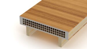
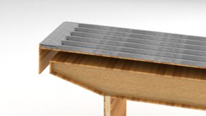
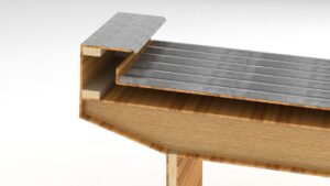
Figures 1-4 Ridge and/or eave opening details as tested by Holz Forschung Austria (HFA) to assess the wind impact on the ventilation rates.
Summary of Laboratory Test Results
Higher temperature gradients showed higher air velocity, ranging from 0.1m/s to 0.4m/s. The detailing of the ridge and
eave showed dependence on the following factors:
• Openings B, C and D showed lower volume airflows than A.
• Opening A using 50mm and 80mm purlins showed increasing airflows with higher roof pitch.
• No influence of roof pitch (3º and 7º) for opening B
• 100mm purlins and opening A showed similar airflow for all roof pitch angles.
• Changing opening A to B and at different roof pitches had a greater influence on airflows at higher differential temperatures.
Results of Outdoor Exposure Test
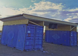
The outdoor exposure test was set up using two identical flat roofs of 12m in length, both with identical eave detail and two ridge details. Detail A, (figure 6) with a ventilation opening downwards and out, and B, (figure 7) up and backwards to the roof. Both roof systems were also tested using a skylight.
Measurements included:
1. Temperature
2. Relative humidity and
3. Selective measurements of air velocity
Measurements of air velocity show a strong correlation to the prevailing winds in direction and speed, with air velocity in the cavity reducing with corresponding still air. If the direction of the wind is aligned with the eave or ridge end of the roof, the air velocity in the cavity is directly proportional to the prevailing winds.
Influence of Direction
The orientation of the roof was shown to be important when comparing measurements in the field. With ridge detail ‘A’ orientated to Northwest and wind direction from the Southeast, higher air velocity was measurable than for ridge detail ‘B’. Detail B showed higher air velocity with wind direction from the Northwest. The air velocity is also complimented by suction effects (wind from the opposite direction).
The measurements of the open cavity showed wind speeds between 0.25 – 1m/s and up to 2-4m/s for direct alignment to the wind direction. Air velocity is higher through wind exposure than through thermal buoyancy.
The results for the interrupted cavity showed lower values. Although the air velocity is still corresponding to the prevailing wind speeds, the measurements did not exceed 0.25m/s, even with direct wind exposure.
Influence of Wind Exposure
In comparison between the wind-exposed and wind-sheltered flat roof eave or ridge, it becomes apparent that direct wind exposure is also reduced by adjacent buildings and other obstructions. The direction of wind is also subject to the urban environment, where wind direction is being altered by buildings.
Draining Liquid Condensate
AS 4200.2 that governs the allowable use of pliable building membranes in Australia allows membranes to be used down to 2° slope. AS/NZS 4200.2 Clause 2.4 states: “Where a pliable building membrane is to be installed as a water control membrane (sarking) in a building, it shall be installed at a slope of no less than 2° to facilitate drainage.”
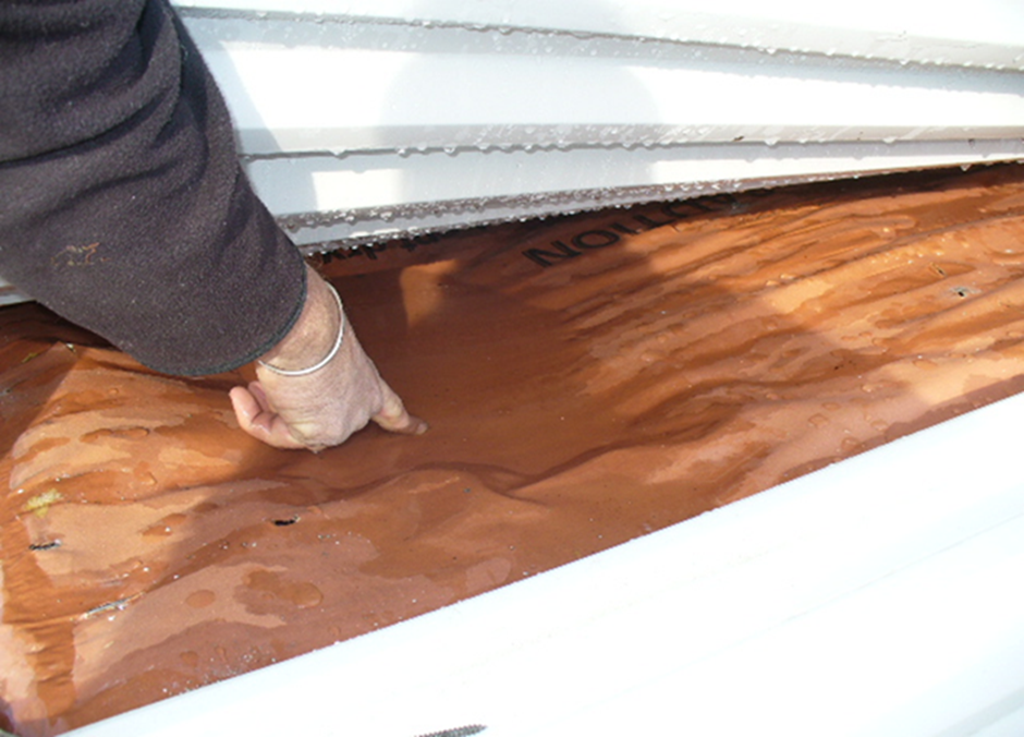
Current practices in Australia and New Zealand allow membranes to be installed over the battens on roofs as low as 2 degrees and 3 degrees, respectively. To drain condensate at these low pitches,
it is necessary that every square centimeter is sloping downhill. This cannot be guaranteed with a flexible membrane only solution. Ponding is highly likely, if not guaranteed, to occur (Figure 9). All flexible membranes must have a rigid board of sufficient mechanical properties to support the water barrier membrane system. The section of the board and its vapour diffusion properties are also of paramount importance.
Rigid Boards
Rigid boards with high water barrier properties tend to have high vapour resistance. Boards with little to no water barrier properties have much higher vapour permeability (Figure 10). These are of value as they allow drying to take place through the rigid board and the vapour permeable SOLITEX EXTASANA ADHERO®.
Controlling Water Vapour
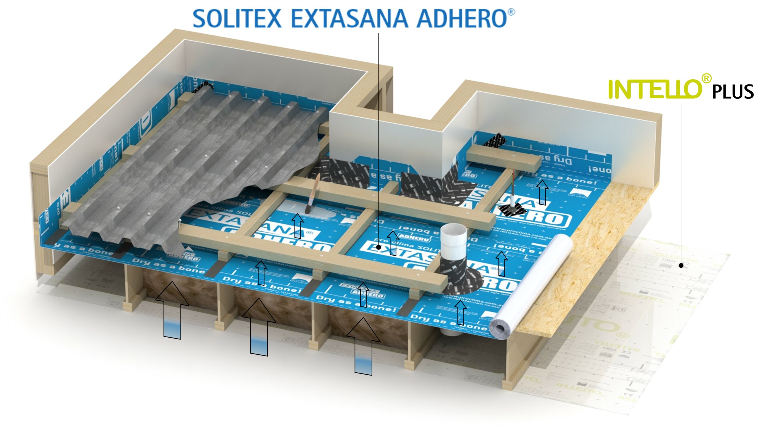
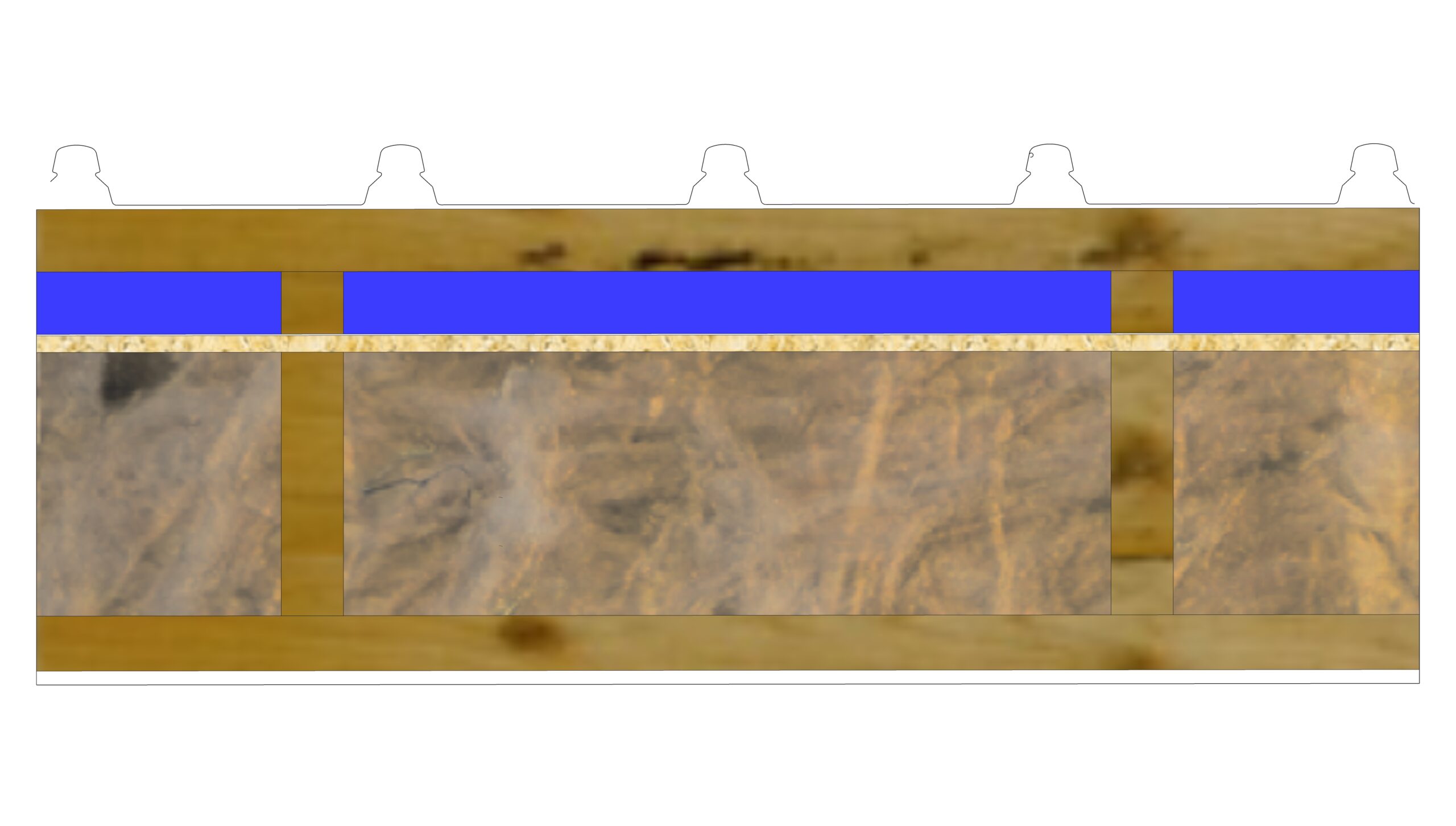
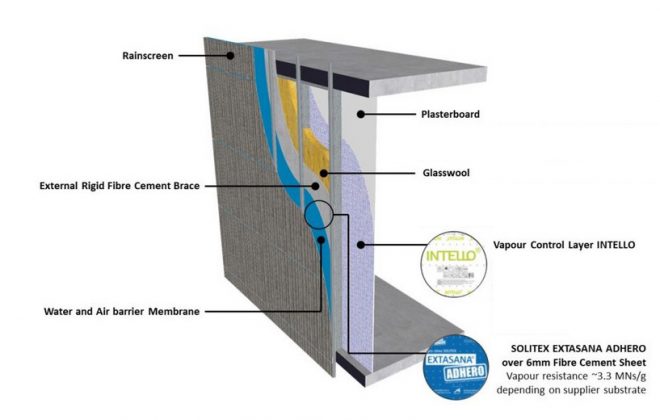
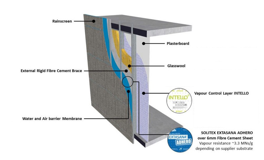
Allowing upward vapour diffusion to the ventilated cavity is highly beneficial to prevent moisture accumulation on the outer layers. The use of an Intelligent Air Barrier (IAB) on the inside of the structure is always recommended to prevent internal water vapour from diffusing into the structure and accumulating in the rigid supporting boards (Figure 11 and Figure 12).
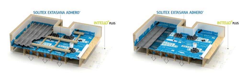
Allowing for drying is best achieved with ventilated cavities behind the cladding assembly on the outside of the SOLITEX EXTASANA ADHERO® and an internal Intelligent Air Barrier (IAB) on the underside of the insulated structure which allows for back diffusion (ASV Part 2). Back diffusion is enhanced with darker coloured roof finishes but will come at the expense of excessive summer solar gains and potential summer cooling issues (ASV Part 3). The vapour variable response of the INTELLO® PLUS membrane is ideal for optimum drying capacity in summer, particularly when used with mid to dark coloured roofs.
Assemblies without ventilated cavities behind the construction will have only inward drying potential and it is critically important these are engineered to ensure the moisture balance is acceptable. Ventilated and non-ventilated roof assemblies should always be checked by a trained WUFI® professional.
WUFI®
The only way to balance the climate-based design with ventilation strategies, roof colour and indoor occupancy profiles is to calculate the potential of moisture accumulation and mould growth using WUFI® software. It is recommended that calculations are carried out using AIRAH DA07 Criteria For Moisture Control Design Analysis in Buildings by a trained WUFI® professional.
Visit www.wufi.com.au for more information.
Ventilation Size
To ensure roof ventilation, it is essential that the counter batten height is appropriately sized to allow sufficient airflow. This results in unobstructed airflow under the fixing battens from eave to ridge.
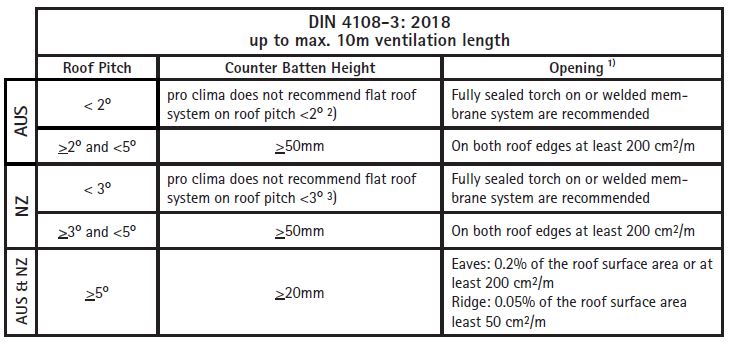
The section area should ideally be higher than the minimum reference value as per Table 1. The figures in Table 1 are taken from DIN 4108-3 which calls for a minimum 50mm high counter battens below 5° and 20mm high counter battens greater than or equal to 5° roof pitch where the ventilation length is up to 10m between eaves and ridge.
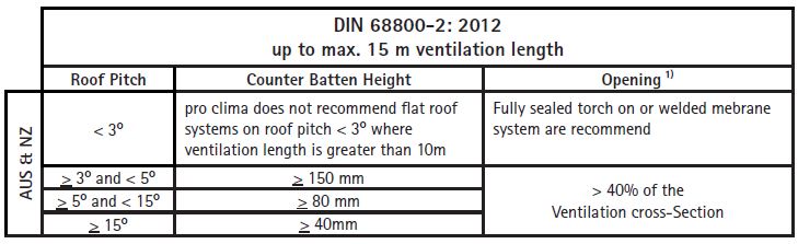
For longer ventilation length up to 15m, DIN 68800-2 calls for a minimum of 150mm high counter battens to achieve sufficient ventilation as per Table 2.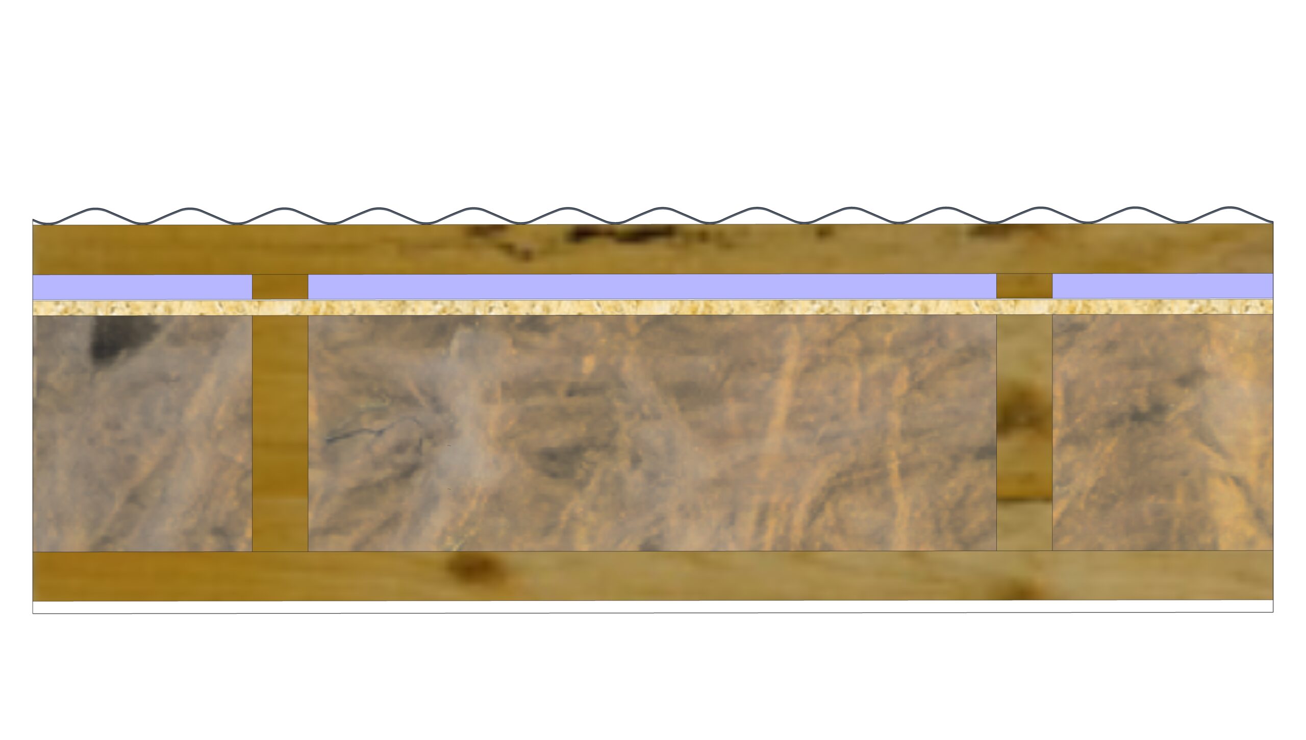
1) Obstruction through mesh or narrowing of the ventilation section must be accounted for when calculating the section area
2) AS 4200.2 allows roofi ng membrnes in Australia down to 2º as long as they facilitate drainage in Australia. SOLITEX EXTASNA ADHERO® systems may be used at this pitch in Australia and always require a rigid board substrate to achieve this.
3) Roof underlays are satisfi ed by Acceptable Solution, NZBC E2/AS1, clause.8.4.5 Roof pitch which limits the slope to 3º
Note: See ASV Part 3 Fighting The Sun for further explaination on batten heights and vent opening sizes.
Summary
The field test shows a direct correlation between air exchange in the roof cavity and the prevailing winds, but can be reduced through:
1. Urban environments (Sheltered)
2. Orientation
3. Eave or ridge detailing
4. Sufficient counter batten height
The tests show the influence of wind-driven ventilation on thermal buoyancy, but the evaluation of cavity ventilation is a complex one.
The requirement of air change in the cavity is to remove moisture from the construction. To evaluate the required air change it is always necessary to consider factors such as roof colour, orientation, and exposure.
The lower the pitch of the roof the higher the risk that moisture accumulates in the battens and therefore the greater the air change requirements need to be.
Code Compliance
Australian Building Code deemed to satisfy provisions of NCC2022 requirements for roof underlays (sarking) are provided in AS4200.2:2017 clause:
3.3.1 (d) The pliable building membrane shall be supported by either-
(i) draping over roof battens, trusses or rafters, with a sag at a slope of not less than 2° to facilitate drainage;
(ii) supporting on safety mesh or other continuous support where available
New Zealand Building Code requirements for the installation of roof underlays are satisfied by Acceptable Solution, NZBC E2/AS1, clause:
8.4.5 Roof pitch
For roofs up to 18 metres in length without end laps, pitches shall be:
a) Corrugated – not less than 8° (1:7).
b) Trapezoidal – not less than:
i) 4° (1:14) where the crest height is less than 27 mm, or
ii) 3° (1:20) where the crest height is 27 mm or higher.
c) Trough profile – not less than 3° (1:20).
marginally better than Australia. It is still impossible to drain without a fully supported & sealed vapour permeable WRB system applied to a vapour permeable rigid board. The board must be sufficient strength and durability characteristics to maintain long-term rigidity and no sagging.
RECOMMENDATIONS
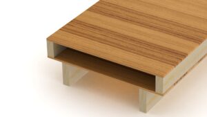
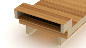
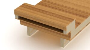
1. Roof underlay placed between the rafters and purlins, or counter battens (to create a cavity above).
2. Insulation and roof underlay at the same angle as roof cladding.
3. Drainage pathway to gutter and a drip edge is always necessary.
4. Roof pitch >3° (refer to building code requirements, AS 4200.2 allows 2°.
5. Rafter lengths (ventilation path) as short as possible and without interruptions, maximum 10m run lenth.
6. Eave and ridge in line with prevailing wind direction.
7. Air- and wind- tight construction detailing (to protect the insulation from wind-wash, which reduces insulation function and R-value).
8. DIN 4180-3 recommend ventilation for low pitch (<5°roof pitches ) for up to 10m roof lengths, must have >50mm counter batten height, with eave ventilation openings equal
to 2% of the total roof area (or minimum 200cm2/m for eave entry).
9. DIN 4180-3 recommend ventilation for low pitch (<5°roof pitches ) for up to 10m roof lengths, must have >50mm counter batten height, with ridge ventilation openings equal
to 0.05% of the total roof area (or minimum 50cm2/m for ridge entry).
10. Obstruction through mesh, or narrowing of the ventilation section should be accounted for when calculating the section area. An Intelligent Air Barrier on the inside of the construction will help mitigate moisture issues in the construction and your system should be assessed by a qualified WUFI® professional.
11. Non-ventilated assemblies are possible but will require careful planning due to the single sided drying capacity. Climate specific risks MUST be assessed by a trained WUFI® professional.
REFERENCES
- [ÖNORM B 3691] ÖNORM B 3691: 2019-05-01 Planning and construction for Roofs, Austrian Standards International. Vienna, 2019
- [ÖNORM B 4119] ÖNORM B 4119: 2018-03-01 Planning and construction for “Sub Roofs” and weathertight layers, Austrian Standards International. Vienna, 2019
- [Holzbau 2019] Holzbau Deutschland Institute e.V. (Hrsg): Flat Roofs in timber construction. Berlin 2019
- [Nusser 2013] Bernd Nusser, Martin Teibinger, Experimental investigations about the air flow in the ventilation layer of low pitched roofs. In: CESBP.2 and CENTRAL EUROPEAN SYMPOSIUM ON BUILDING PHYSICS.S. 1-8 Vienna 2013.
- [Knust 2019] Knust Björn, Thomas Bednar: Determination of thermal induced volume air flow in the cavity of low pitched roofs, Thesis TU Vienna 2019
- [Leitner 2018] Stefan Leitner, Georg Aichinger, Bernard Fürpaß, Johann Spiessberger, WKO Oberösterreich: The low pitch Roof, Air Flow: Experiments, measurements and simulation. Linz 2018
- [SIA 271] SIA 271:2017: Weathertightness in construction, Swiss Association of Engineers and Architects, Zürich 2007

